| Application |
Typical network position |
Metro access and short-reach DCI links |
Metro-core and regional links |
Long regional links with higher optical loss |
Multi-channel networks requiring inventory flexibility |
Match the optical budget to the actual link, rather than selecting the longest-distance module by default. |
| Form Factor |
Module type |
SFP+ or equivalent 10G pluggable module |
SFP+ or equivalent 10G pluggable module |
SFP+ or equivalent 10G pluggable module |
Tunable SFP+ or equivalent tunable pluggable module |
Confirm host compatibility, electrical interface, management interface, and coding requirements. |
| Data Rate |
Line-side bit rate |
10 Gb/s nominal; commonly supports 10GbE or STM-64/OC-192 protocols |
10 Gb/s nominal; commonly supports 10GbE or STM-64/OC-192 protocols |
10 Gb/s nominal; commonly supports 10GbE or STM-64/OC-192 protocols |
10 Gb/s nominal, subject to host and firmware support |
Select a module with the required protocol support and confirm actual host interoperability. |
| Wavelength |
Operating wavelength |
Fixed C-band DWDM wavelength, typically near 1530–1565 nm |
Fixed C-band DWDM wavelength, typically near 1530–1565 nm |
Fixed C-band DWDM wavelength, typically near 1530–1565 nm |
Selectable C-band wavelength, commonly based on an ITU-T DWDM grid |
Use a wavelength compatible with the mux/demux port, channel plan, and optical amplifier passband. |
| Channel Spacing |
Grid compatibility |
Typically 100 GHz or 50 GHz fixed-grid spacing |
Typically 100 GHz or 50 GHz fixed-grid spacing |
Typically 100 GHz or 50 GHz fixed-grid spacing |
Commonly supports multiple fixed-grid channels; some designs support flexible-grid operation |
The transceiver grid must match the passive optical filter and the network channel plan. |
| Transmitter Power |
Average optical output power |
Approximately -1 to +4 dBm |
Approximately 0 to +4 dBm |
Approximately 0 to +5 dBm |
Approximately 0 to +5 dBm, depending on wavelength and tuning state |
Check minimum and maximum power across temperature, wavelength, and end-of-life conditions. |
| Receiver Sensitivity |
Minimum receiver input level |
Typically better than -15 dBm |
Typically approximately -23 to -24 dBm |
Typically approximately -24 to -26 dBm |
Typically approximately -23 to -26 dBm |
Use the guaranteed sensitivity at the target bit-error rate, not a typical laboratory value. |
| Receiver Overload |
Maximum receiver input level |
Typically approximately -3 to 0 dBm |
Typically approximately -3 to 0 dBm |
Typically approximately -3 to 0 dBm |
Typically approximately -3 to 0 dBm |
Keep received power below overload. Add an attenuator when amplifier output is too high. |
| Optical Budget |
Nominal power budget |
Approximately 14–19 dB |
Approximately 23–28 dB |
Approximately 24–31 dB |
Approximately 23–31 dB |
Calculate fiber loss, connector loss, splice loss, mux/demux loss, repair margin, and aging margin together. |
| Link Margin |
Recommended engineering reserve |
At least 3 dB after all passive losses |
At least 3 dB after all passive losses |
Typically 3–5 dB because of longer spans and repair uncertainty |
At least 3 dB, plus margin for wavelength-dependent performance |
Avoid operating at the theoretical power-budget limit; insufficient margin reduces service stability. |
| Fiber Type |
Supported optical fiber |
Single-mode fiber, commonly G.652.D or G.655 |
Single-mode fiber, commonly G.652.D or G.655 |
Single-mode fiber, commonly G.652.D or G.655 |
Single-mode fiber compatible with the complete DWDM line system |
Verify attenuation, chromatic dispersion, nonlinear effects, and fiber type across the entire route. |
| Optical Connector |
Standard interface |
Duplex LC, commonly UPC or APC according to system design |
Duplex LC, commonly UPC or APC according to system design |
Duplex LC, commonly UPC or APC according to system design |
Duplex LC, commonly UPC or APC according to system design |
Do not mix UPC and APC interfaces. Connector polish must match the patch panel and passive equipment. |
| Laser Technology |
Transmitter source |
Temperature-controlled EML or equivalent narrow-linewidth laser |
Temperature-controlled EML or equivalent narrow-linewidth laser |
High-performance EML or equivalent design with dispersion control |
Tunable laser with wavelength-locking and thermal-control circuitry |
Prefer a narrow-linewidth, wavelength-stable transmitter for filtered DWDM systems. |
| Spectral Performance |
Side-mode suppression ratio |
Typically at least 30 dB |
Typically at least 30 dB |
Typically at least 30 dB |
Typically at least 30 dB across the tuning range |
Higher suppression improves resistance to adjacent-channel interference. |
| Spectral Performance |
Wavelength accuracy |
Fixed-grid tolerance commonly within ±0.05 nm |
Fixed-grid tolerance commonly within ±0.05 nm |
Fixed-grid tolerance commonly within ±0.05 nm |
Commonly within ±0.05 nm after wavelength locking |
Confirm accuracy over the complete operating temperature range and product lifetime. |
| Dispersion |
Chromatic-dispersion tolerance |
Typically adequate for metro distances; verify route-specific limits |
Usually specified for approximately 80 km-class links; commonly around 1,600 ps/nm or higher |
Often specified at approximately 2,000 ps/nm or higher, depending on design |
Must be checked for every supported channel and operating condition |
Use a dispersion-compensation or coherent solution when the calculated route exceeds the module specification. |
| Receiver Performance |
BER target |
Typically specified at or below 1 × 10⁻¹² before forward-error correction |
Typically specified at or below 1 × 10⁻¹² before forward-error correction |
Typically specified at or below 1 × 10⁻¹² before forward-error correction |
Typically specified at or below 1 × 10⁻¹² before forward-error correction |
Compare test conditions, optical power, extinction ratio, and receiver type before comparing BER values. |
| Extinction Ratio |
Transmitter extinction ratio |
Typically at least 8.2 dB |
Typically at least 8.2 dB |
Typically at least 8.2 dB |
Typically at least 8.2 dB across the tuning range |
Adequate extinction ratio supports clean eye diagrams and reliable receiver decisions. |
| Operating Temperature |
Commercial temperature range |
0 to 70 °C |
0 to 70 °C |
0 to 70 °C |
0 to 70 °C |
Use industrial-temperature versions only when the enclosure environment requires them. |
| Operating Temperature |
Extended temperature option |
-40 to 85 °C may be available |
-40 to 85 °C may be available |
-40 to 85 °C may be available |
-40 to 85 °C may be available, but tuning stability must be verified |
Select based on the measured temperature inside the host, not only the room temperature. |
| Temperature Monitoring |
Diagnostic functions |
Digital monitoring of temperature, voltage, bias current, Tx power, and Rx power |
Digital monitoring of temperature, voltage, bias current, Tx power, and Rx power |
Digital monitoring of temperature, voltage, bias current, Tx power, and Rx power |
All standard diagnostics plus wavelength and tuning-status monitoring |
Require calibrated alarm thresholds and confirm compatibility with the host management system. |
| Power Consumption |
Typical module power |
Usually below 1.5 W |
Usually approximately 1.5–2.0 W |
Usually approximately 1.5–2.5 W |
Commonly approximately 2.0–3.5 W because of tuning and thermal-control circuits |
Check power draw at maximum temperature and maximum optical output for accurate thermal planning. |
| Thermal Design |
Host cooling requirement |
Standard switch airflow is generally sufficient |
Requires stable airflow and adequate cage ventilation |
Requires careful airflow and thermal validation |
Requires the most stringent airflow and heat-dissipation conditions |
Leave adequate spacing around high-power modules and validate the host inlet temperature. |
| Laser Safety |
Safety classification |
Normally Class 1 laser product under applicable safety standards |
Normally Class 1 laser product under applicable safety standards |
Normally Class 1 laser product under applicable safety standards |
Normally Class 1 laser product under applicable safety standards |
Follow site procedures for invisible laser radiation and never inspect an active connector directly. |
| Interoperability |
Host and network compatibility |
Confirm 10G electrical compliance and fixed wavelength coding |
Confirm 10G electrical compliance, wavelength coding, and optical budget |
Confirm host support for high-power and long-reach operation |
Confirm tunable control, supported channel count, grid, and management commands |
Test with the actual switch, mux/demux, amplifier, and remote transceiver before large-scale deployment. |
| Best Use Case |
Recommended deployment |
Short metro links with moderate insertion loss |
Most common choice for regional DWDM transport |
Routes requiring additional margin or longer spans |
Networks with frequent wavelength reassignment and reduced spare inventory |
Choose the simplest profile that meets the calculated optical and environmental requirements. |

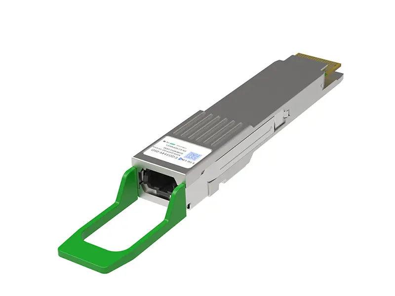 400G
400G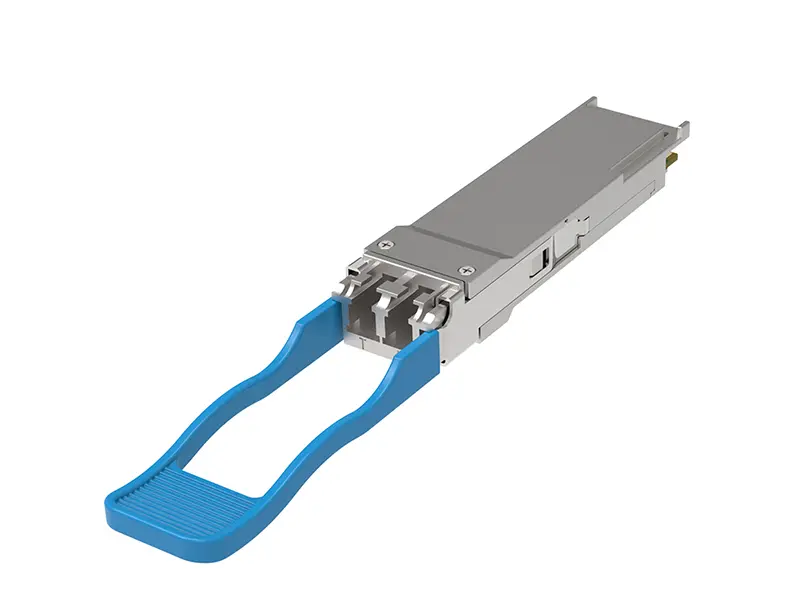 200G
200G 100G
100G 40G
40G 25G
25G 10G
10G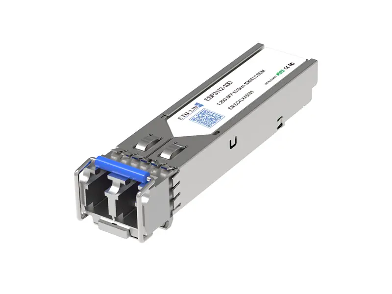 1G
1G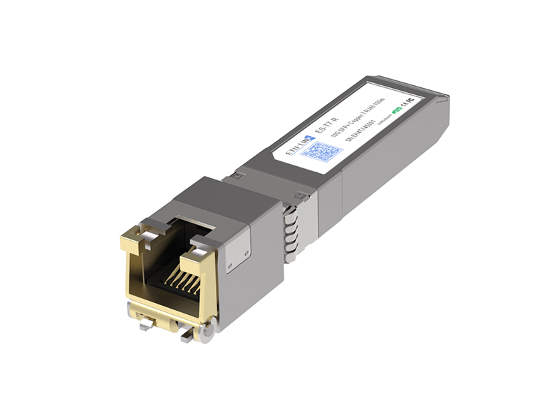 COPPER-T
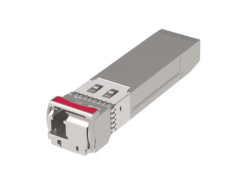 Other
Other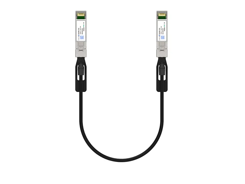 10G SFP+ DAC
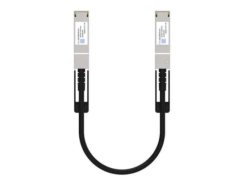 40G QSFP+ DAC
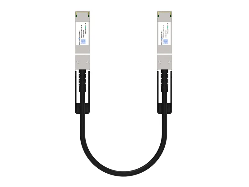 56G QSFP+ DAC
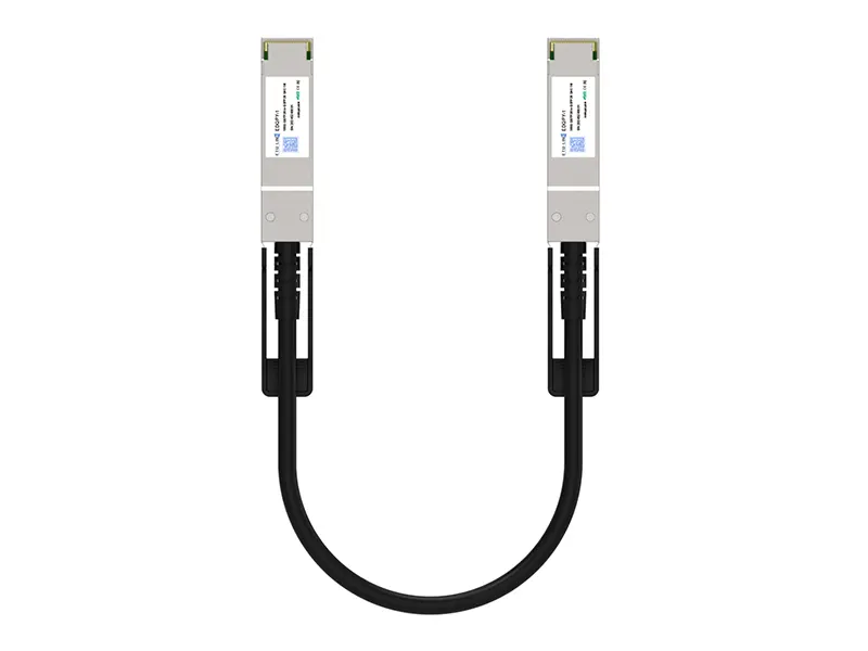 100G QSFP28 DAC
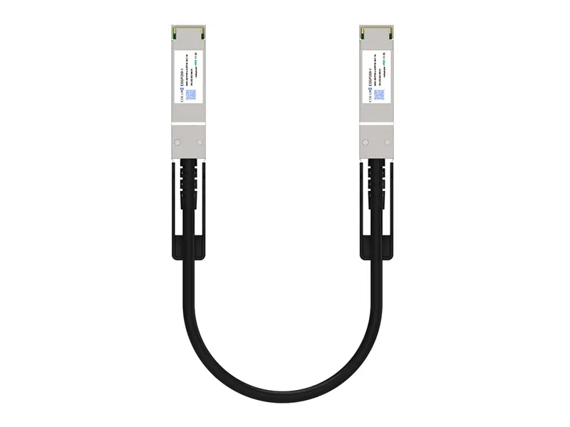 200G QSFP56 DD DAC
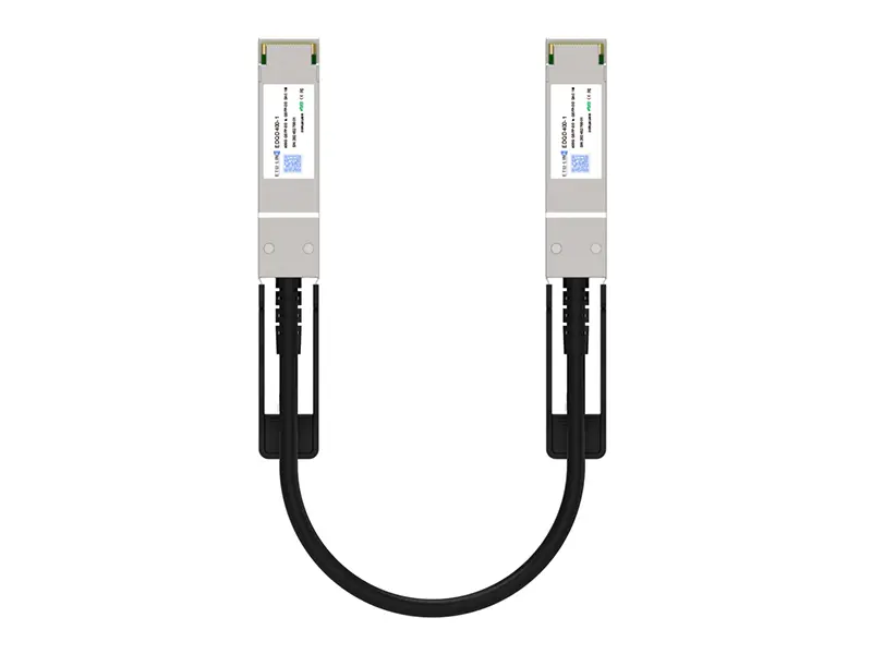 400G QSFP DD DAC
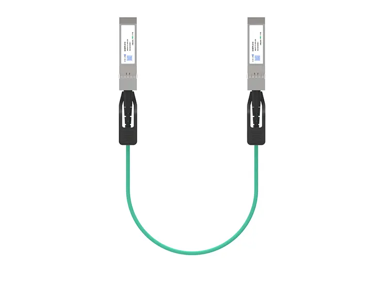 10G SFP+ AOC
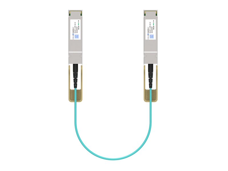 40G QSFP+ AOC
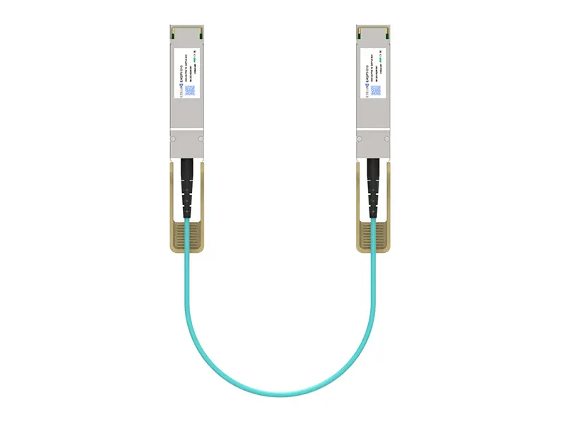 100G QSFP28 AOC
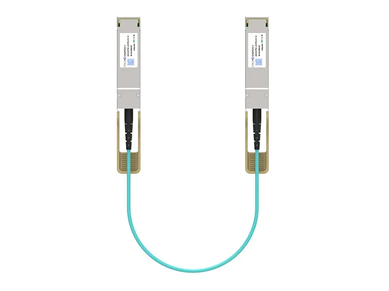 200G QSFP56 AOC
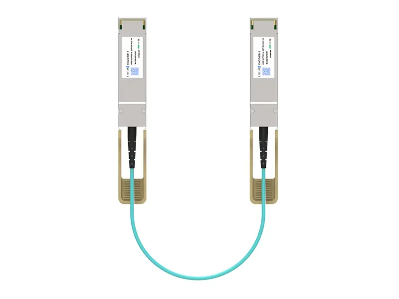 400G QSFP-DD AOC
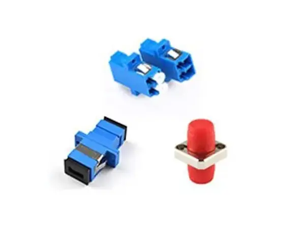 Adapter Details
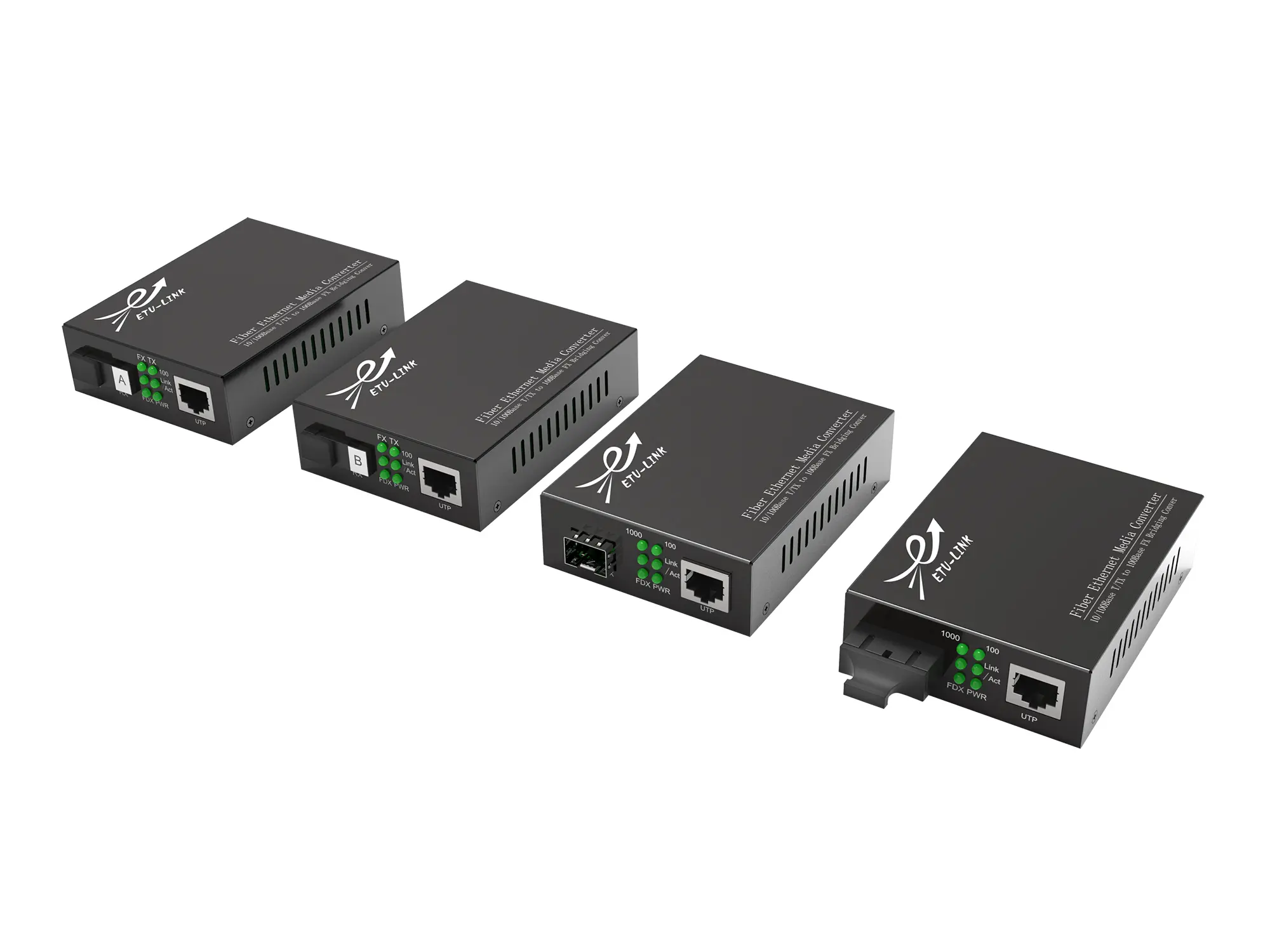 Media Converter