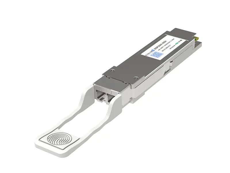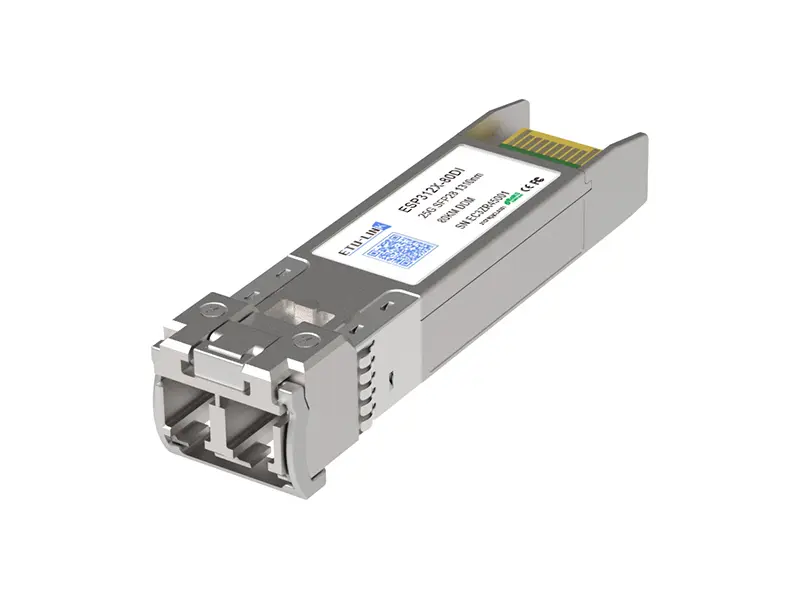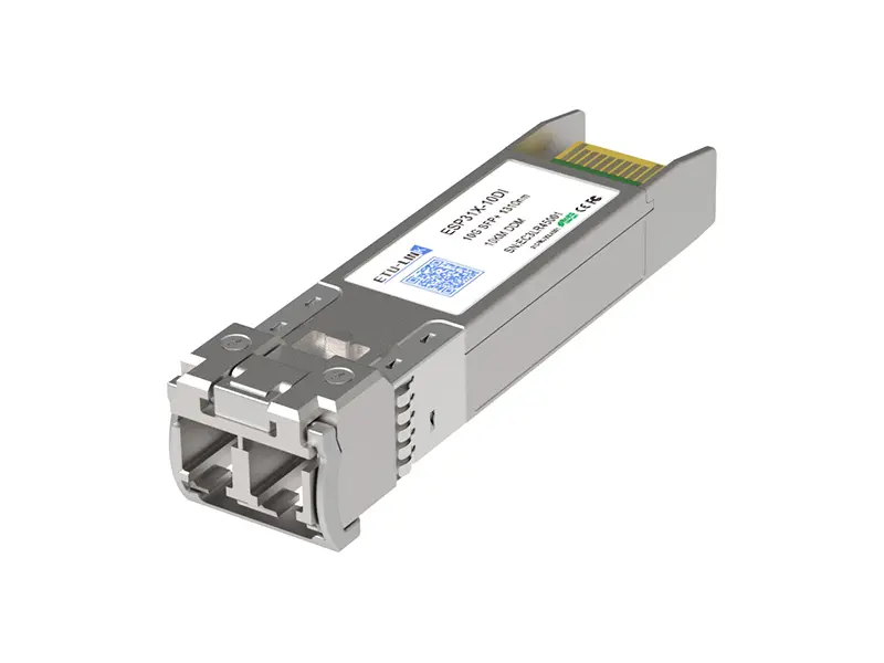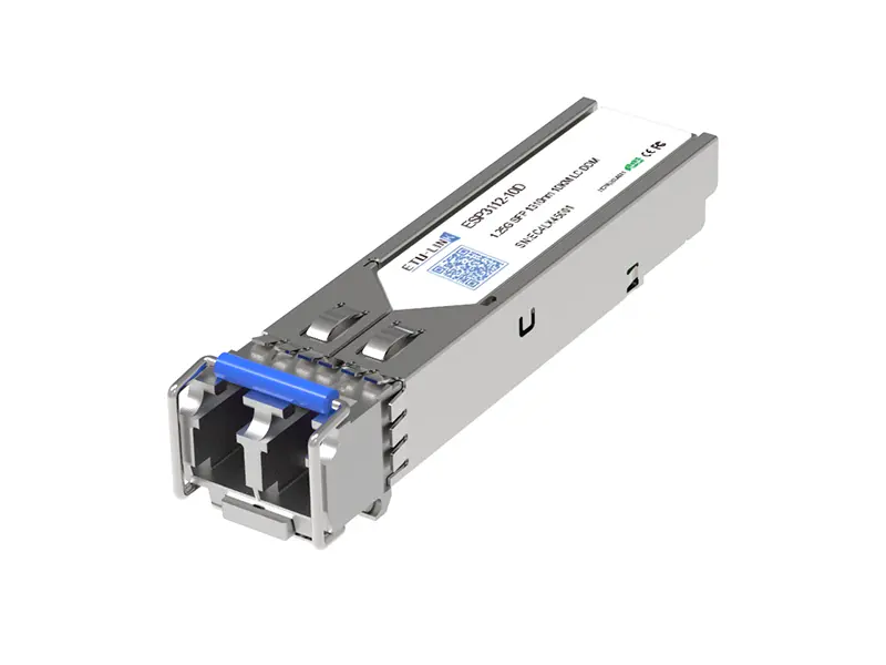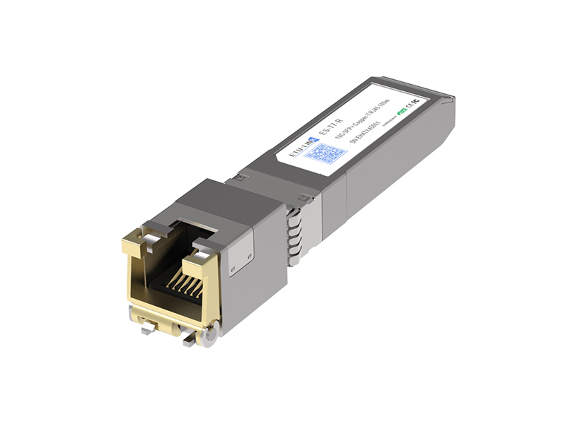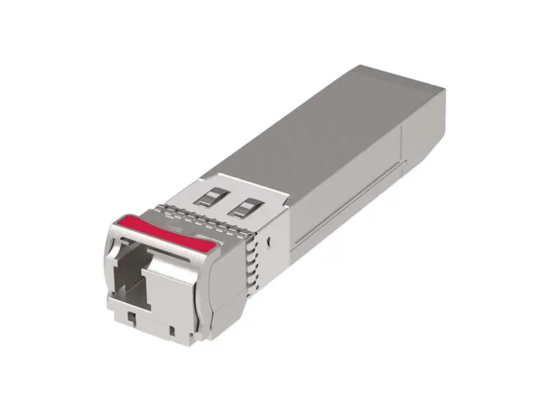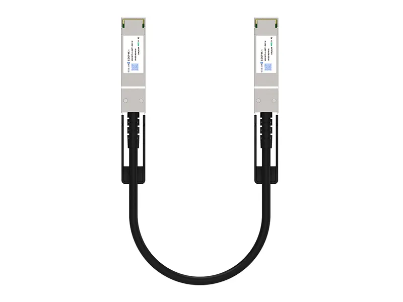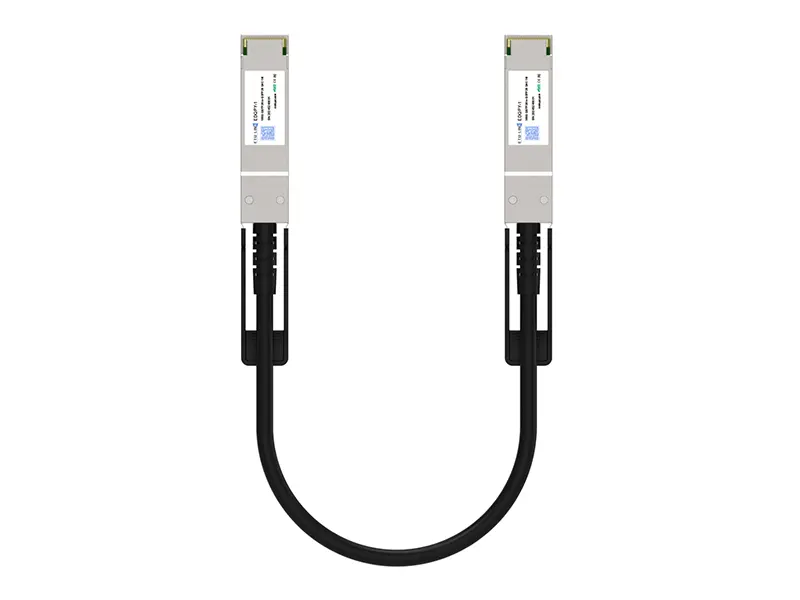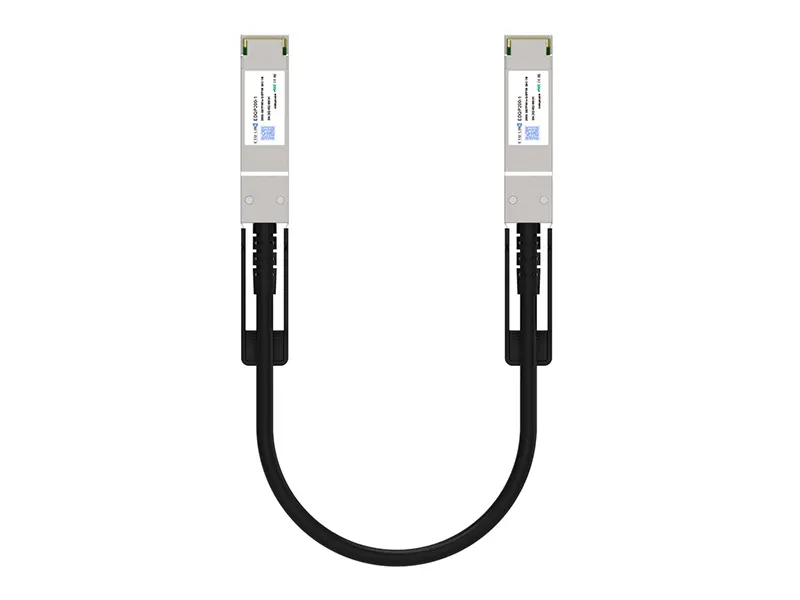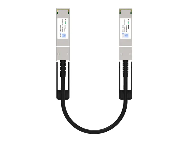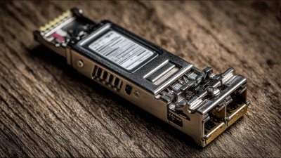
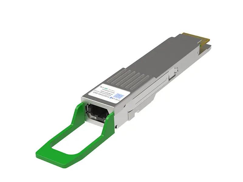
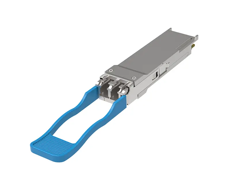
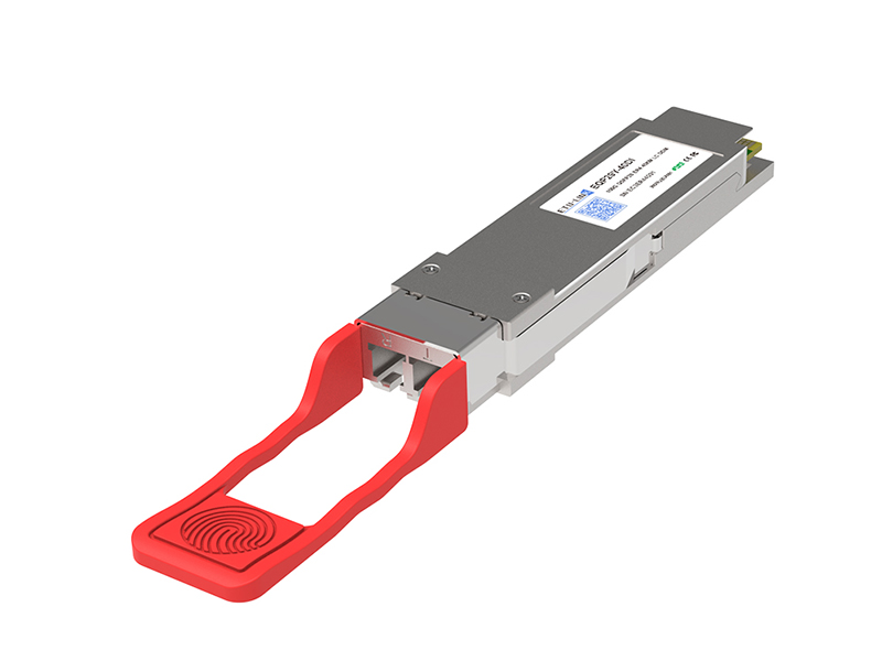
A 10G DWDM 80km link is built for high-capacity transmission across long fiber routes. It carries 10 gigabits per second over approximately 80 kilometers, while DWDM combines several wavelengths through one fiber pair. Each wavelength acts like an independent traffic lane. More lanes mean greater capacity without installing new cable.
The system normally includes 10G DWDM transceivers, multiplexers, demultiplexers, optical amplifiers, and monitoring equipment. A transceiver converts electrical data into a precise optical signal. The multiplexer then combines multiple colors of light. At the destination, the demultiplexer separates them again. Simple in principle. Careful in practice.
Peter J. Winzer, a leading optical-communications researcher, once expressed a useful engineering lesson: “A good optical link is designed as a system, not as a collection of parts.” That principle fits 10G DWDM 80km deployment closely. Fiber loss, connector quality, dispersion, amplifier noise, and power balance all affect performance. A strong transmitter cannot repair poor optical planning.
In a real installation, technicians may inspect patch-panel cleanliness, measure insertion loss, and verify received power at both ends. Temperature changes can also influence equipment stability. The advertised 80km reach is not always guaranteed. Actual distance depends on fiber quality, channel spacing, network architecture, and the transceiver’s optical budget.
This guide explains what 10G DWDM 80km means, how its wavelength channels work, and where practical limitations appear. Some designs look efficient on paper. Field measurements may disagree. That gap deserves attention.

10G DWDM 80km describes an optical communication system that carries data at 10 gigabits per second across distances of up to 80 kilometers. The 10G rate usually applies to each wavelength channel. DWDM, or Dense Wavelength Division Multiplexing, places several light wavelengths inside one fiber. Each wavelength acts like a separate traffic lane. This design increases fiber capacity without installing additional cables.
The system uses optical transceivers to convert electrical signals into light. A multiplexer combines multiple wavelengths at the transmission site. At the receiving site, a demultiplexer separates them again. The signals commonly operate in the 1550 nm band, where fiber attenuation is relatively low. For an 80 km link, engineers may also consider optical amplifiers, dispersion control, forward error correction, and channel spacing.
That distance is conditional.
Actual performance depends on fiber loss, connector quality, splice points, dispersion, and receiver sensitivity. A clean link with low-loss components may operate reliably, while an older fiber route can reduce the practical margin. Power measurements should be taken at both ends before deployment. Engineers also need to check wavelength compatibility and optical power levels, because excessive power can overload a receiver. The specification looks simple, but field conditions often make it less exact. A careful link budget remains essential.

What Is 10G DWDM 80km and How Does It Work?
Key Components of a 10G DWDM 80km System
A 10G DWDM 80km link carries 10 gigabits per second on one optical wavelength. Multiple wavelengths share one fiber pair. The system begins with a 10G optical transceiver, converting electrical data into a stable laser signal. A multiplexer combines channels at the network edge. An optical demultiplexer separates them at the receiving site.
The fiber forms the long middle section. ITU-T G.652 guidance places typical attenuation near 0.2 dB per kilometer around 1550 nm. Across 80 kilometers, fiber loss can approach 16 dB before connector, splice, and aging penalties. That figure is practical, not decorative. Engineers still need a complete link budget. Optical amplifiers may restore power, while dispersion control limits pulse spreading. Yet these choices depend on modulation, fiber quality, and channel spacing.
The wavelength grid follows ITU-T G.694.1, commonly using 100 GHz or 50 GHz spacing. A 50 GHz grid supports more channels but requires tighter filtering. The optical supervisory channel provides alarms and performance checks. The 2024 Global Bandwidth Research Service reported approximately 1,479 Tbps of installed international bandwidth worldwide. That growth supports DWDM adoption, but capacity alone can mislead. Real deployment also depends on insertion loss, receiver sensitivity, temperature, and maintenance access. Field measurements often expose assumptions that looked perfect on paper.
A 10G DWDM 80km link sends data as precisely controlled pulses of light. The transmitter converts electrical Ethernet signals into a 10Gbps optical stream. A narrow-linewidth laser places that stream on one wavelength. Several wavelengths then travel through the same fiber.
The multiplexer combines these colored signals before transmission. At the remote site, a demultiplexer separates them again. Each receiver filters its assigned wavelength, converts light into electrical signals, and restores the original data.
Forward error correction can repair limited bit errors. Timing recovery keeps the data stream stable.
Distance creates practical problems. Eighty kilometers of fiber may introduce about 20dB of attenuation, depending on the cable and operating conditions. Splices, connectors, bends, and aging add more loss.
An optical amplifier may restore signal power, but excessive amplification can raise noise and reduce the optical signal-to-noise ratio. Dispersion also spreads pulses, making neighboring bits harder to distinguish.
Field testing matters.
Engineers normally check transmit power, receiver sensitivity, wavelength accuracy, and span loss with optical test equipment. A clean laboratory diagram can hide dirty connectors or unexpected bends.
Not every 80km route needs identical components; fiber quality, channel count, and margin change the design. This is where planning can be imperfect. A link may work during installation, yet fail later when temperature shifts or additional channels increase interference. Monitoring those conditions keeps the transmission dependable.
A 10G DWDM 80km link carries about 10 gigabits per second on each optical wavelength. DWDM combines several wavelengths through one fiber, often within the C-band around 1530–1565 nanometers. Each channel needs accurate wavelength spacing, stable transmit power, and suitable receivers. Small wavelength errors can increase crosstalk between neighboring channels.
Optical power determines whether the signal reaches the far end clearly. Engineers calculate the power budget from transmitter output, fiber attenuation, connector loss, splice loss, and receiver sensitivity. For example, 80 kilometers of standard single-mode fiber may introduce roughly 16–20 dB of fiber loss, depending on wavelength and conditions. Amplification may restore power, but excessive power creates nonlinear effects and can worsen signal quality. OSNR also matters, especially when multiple channels share the fiber. More power is not always better.
Dispersion becomes another limitation at 10G speeds. Over long fiber spans, pulses spread and may overlap. Dispersion compensation or suitable receiver processing can reduce this problem. Yet the 80km label can mislead. Real routes include bends, aging connectors, repairs, and temperature changes. A link that works in a laboratory may need extra margin in the field. I would not approve the distance from fiber length alone. Measured loss, received power, dispersion, and OSNR should be checked together. Small installation details matter.
10G DWDM 80km is commonly used when one fiber pair must carry several 10Gbps channels across a metropolitan area. Dense wavelength division multiplexing places separate optical signals on different wavelengths. A multiplexer combines them, while a demultiplexer separates them at the far end.
Typical applications include data center interconnection, carrier aggregation, mobile backhaul, and links between regional offices. Utility networks may also use it along substations and control centers. An 80km path can connect sites across a city, but the actual reach depends on fiber quality and optical loss.
Deployment planning needs more than a distance estimate. Engineers should verify the fiber route, connector count, splice loss, dispersion, and optical signal-to-noise ratio. An optical power budget is essential. Some routes work without amplification, while older fiber may need an in-line amplifier or dispersion compensation. The exact design depends on the transceiver and channel plan.
Check wavelength compatibility before installation. Mux and demux components must support the selected spacing and channel count. Temperature changes also matter in outdoor cabinets. Monitoring ports can reveal gradual power decline before service fails.
Distance labels can mislead.
Field testing often exposes problems that drawings miss. A clean 78km route may perform worse than a longer route with fewer splices. Engineers should test insertion loss and receive power at both ends. Allowing spare channels is practical, although it increases unused capacity and initial cost. That trade-off deserves review, not assumption.
| Data Dimension | Typical Value or Range | Technical Description and Deployment Relevance |
|---|---|---|
| Transmission Rate | 10 Gbit/s per wavelength | A single optical channel carries data at approximately 10 gigabits per second. The effective user throughput is slightly lower because of Ethernet, forward-error-correction, and other protocol overheads. |
| Nominal Reach | Up to 80 km | The 80 km rating is a typical engineering target for an unregenerated span. Actual distance depends on fiber attenuation, connector and splice losses, dispersion, optical signal-to-noise ratio, amplifier settings, and link-margin requirements. |
| Fiber Type | Standard single-mode fiber | Deployment normally uses single-mode optical fiber designed for long-distance transmission. Existing fiber routes may be reused if their loss, reflections, chromatic dispersion, and repair history meet the optical budget. |
| Wavelength Band | C-band, approximately 1,530–1,565 nm | The C-band is widely used for DWDM because optical fiber attenuation is relatively low in this region and optical amplifiers can provide efficient gain across much of the band. |
| Channel Spacing | Commonly 100 GHz or 50 GHz | Closer channel spacing increases spectral efficiency but requires stricter wavelength accuracy, filtering performance, and control of nonlinear effects. The selected spacing should match the transceiver and multiplexer design. |
| Wavelength Multiplexing | Multiple optical channels on one fiber pair | A DWDM multiplexer combines separate wavelengths onto the same fiber. At the receiving site, a demultiplexer separates the wavelengths so each channel can be delivered to its corresponding optical interface. |
| Typical Optical Budget | Often about 20–30 dB, design dependent | The available budget must cover fiber loss, splice loss, connector loss, patch-panel loss, aging allowance, and engineering margin. The exact value varies by optical module class and system architecture. |
| Fiber Attenuation Reference | Approximately 0.20–0.25 dB/km near 1,550 nm | For an 80 km route, fiber attenuation alone may represent roughly 16–20 dB before adding connectors, splices, and other passive losses. Measured route loss should be used for final validation rather than distance alone. |
| Chromatic Dispersion | Must be checked across the full route | Different wavelengths travel at slightly different speeds in the fiber, causing pulse spreading. Dispersion compensation, electronic compensation, or a suitable receiver design may be required depending on the fiber type and transceiver tolerance. |
| Optical Amplification | Optional; commonly used when the loss budget requires it | An optical amplifier can extend the practical span or compensate for passive component loss, but it also adds amplified spontaneous emission noise. Amplifier gain, output power, and operating margin must be balanced against receiver sensitivity and nonlinear effects. |
| Regeneration | Usually not required within a qualified 80 km span | Electrical regeneration may be needed when the route exceeds the supported optical budget or when accumulated dispersion and noise cannot be corrected optically. A measured end-to-end test should confirm whether regeneration is necessary. |
| Common Applications | Metro networks, data-center interconnects, regional backbones, and enterprise WANs | The technology is suitable for connecting sites over metropolitan or regional distances while increasing capacity on existing fiber. It is often used for aggregation links, storage connectivity, mobile transport, and high-capacity campus interconnection. |
| Point-to-Point Deployment | Two terminal sites connected by a dedicated fiber route | This is the simplest architecture: one site multiplexes the wavelengths and the other site demultiplexes them. It offers straightforward troubleshooting and predictable optical performance. |
| Ring or Protected Network | Dual-route or ring-based protection | A protected topology can maintain service after a fiber cut or equipment failure. Protection planning should account for switching time, optical power differences between routes, and the effect of additional passive components. |
| Power and Cooling | Depends on transceivers, amplifiers, and chassis density | High-density DWDM equipment may require additional rack power and airflow. Equipment rooms should provide suitable temperature control, grounding, cable management, and sufficient space for maintenance. |
| Commissioning Tests | Insertion loss, optical power, wavelength, OSNR, and BER | Recommended verification includes an optical time-domain reflectometer test, end-to-end insertion-loss measurement, transmit and receive power checks, wavelength verification, optical signal-to-noise ratio testing, and bit-error-rate validation under expected traffic conditions. |
| Maintenance Requirements | Routine optical inspection and performance monitoring | Clean connectors, stable patching, accurate labeling, and trend monitoring help prevent power drift and intermittent faults. Optical connectors should be inspected and cleaned before connection, especially at high-density patch panels. |
| Key Deployment Risk | Insufficient margin caused by unmeasured loss or aging | A route that meets the nominal 80 km distance may still fail if connectors, splices, bends, amplifiers, or passive filters consume the available margin. A practical design should include a documented engineering reserve for future degradation and changes. |
| Scalability | Additional wavelengths can increase capacity | DWDM can expand capacity by activating unused channels on the same fiber, provided that the multiplexer, demultiplexer, optical budget, channel plan, and system software support the additional wavelengths. |
Engineering note: Values are representative planning figures. Final deployment should be based on measured fiber characteristics, the selected optical components, applicable transmission standards, and a complete end-to-end link-budget calculation.