
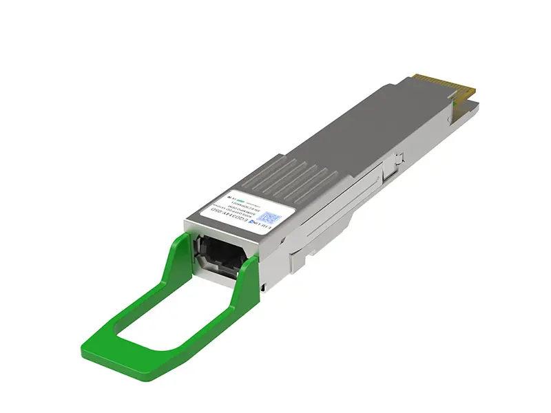
 400G
400G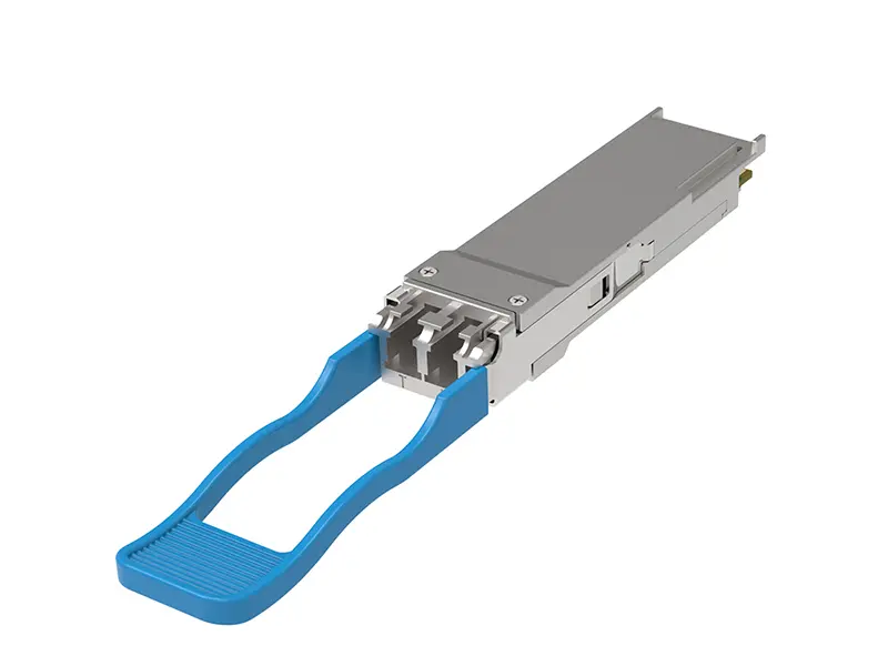 200G
200G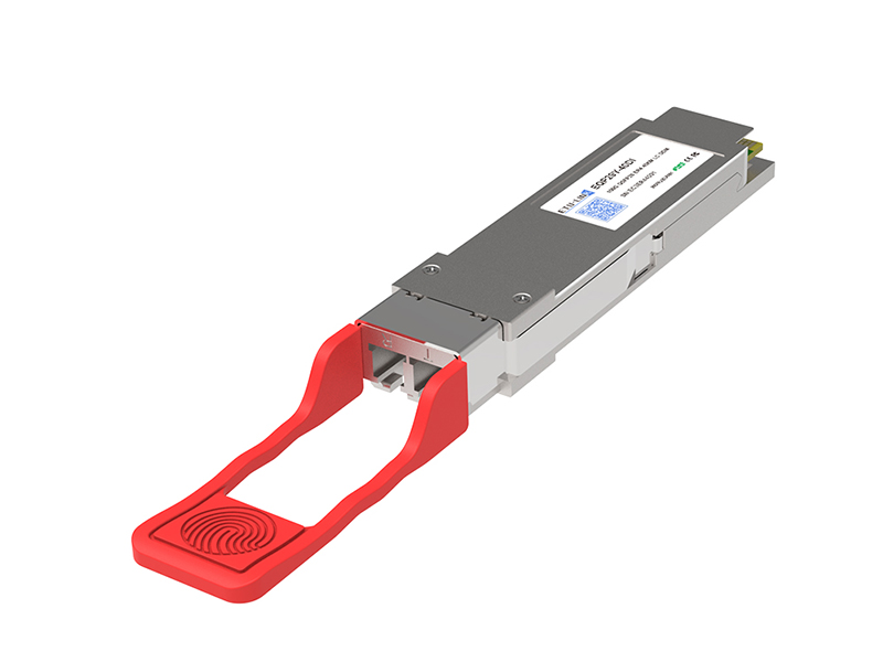 100G
100G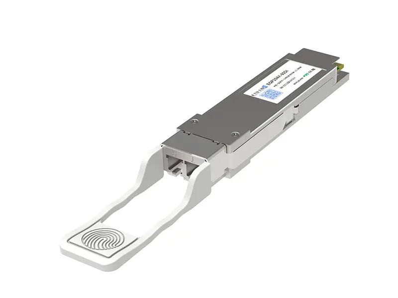 40G
40G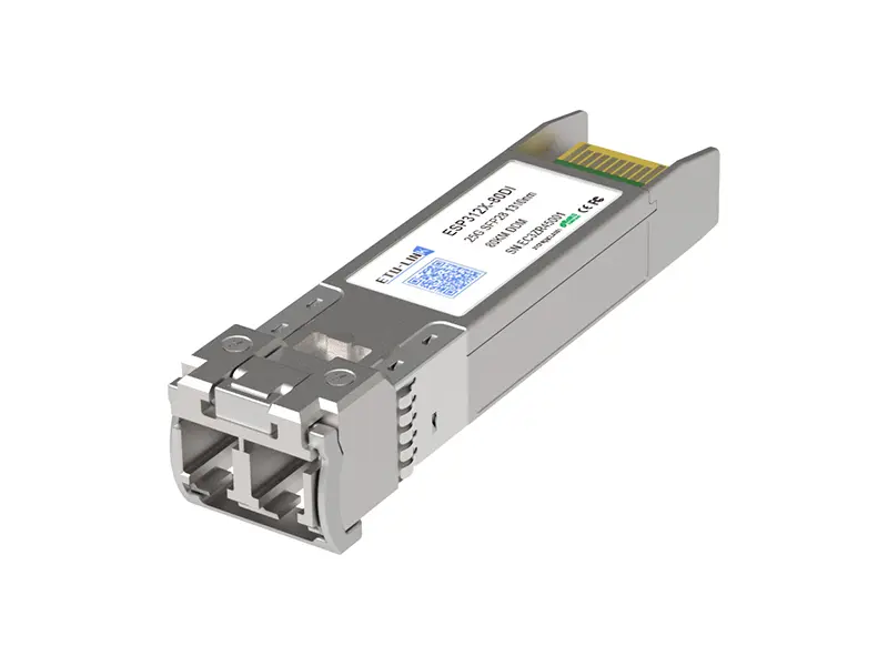 25G
25G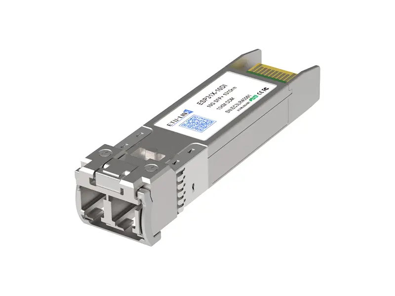 10G
10G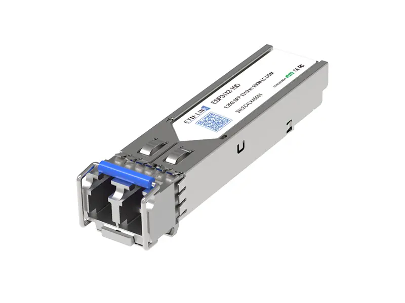 1G
1G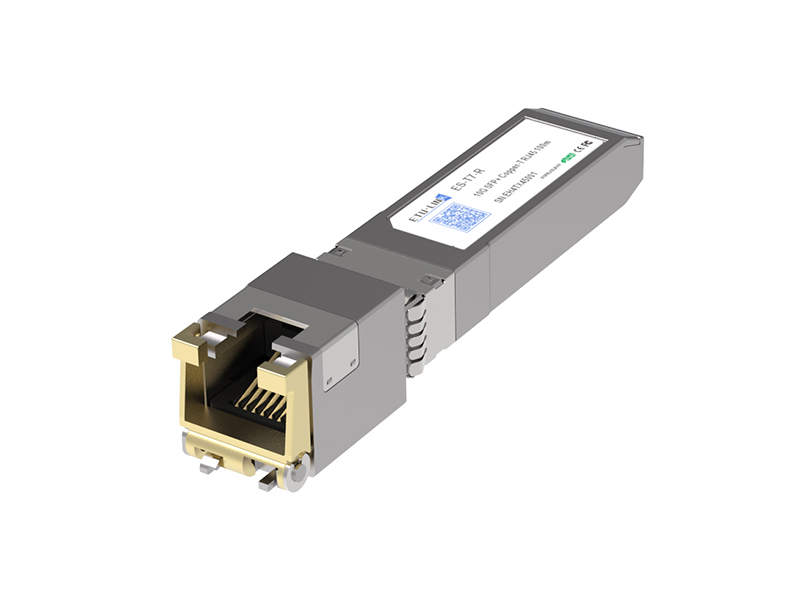 COPPER-T
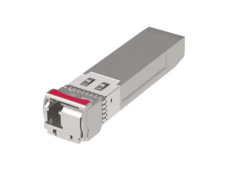 Other
Other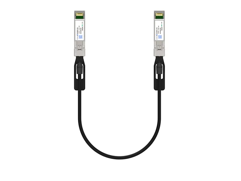 10G SFP+ DAC
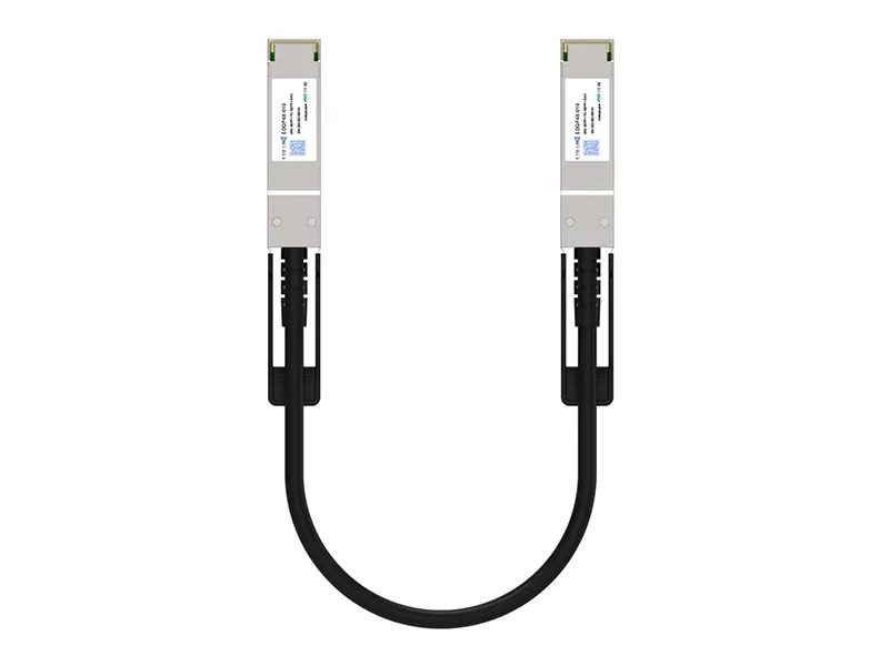 40G QSFP+ DAC
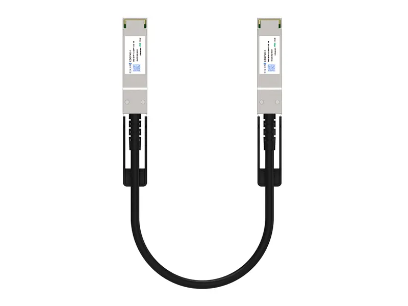 56G QSFP+ DAC
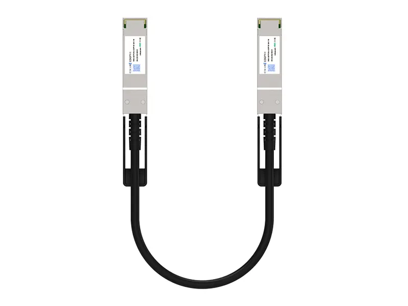 100G QSFP28 DAC
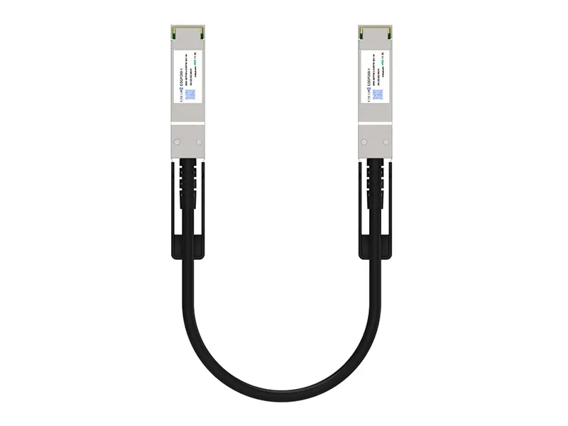 200G QSFP56 DD DAC
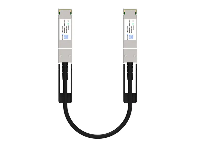 400G QSFP DD DAC
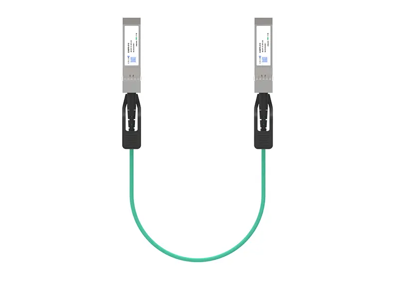 10G SFP+ AOC
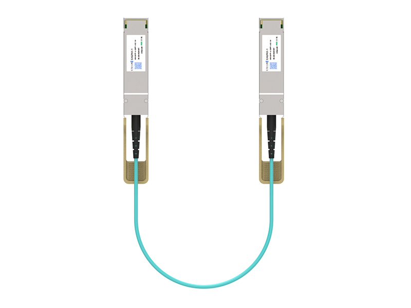 40G QSFP+ AOC
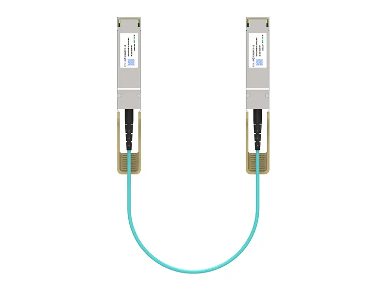 100G QSFP28 AOC
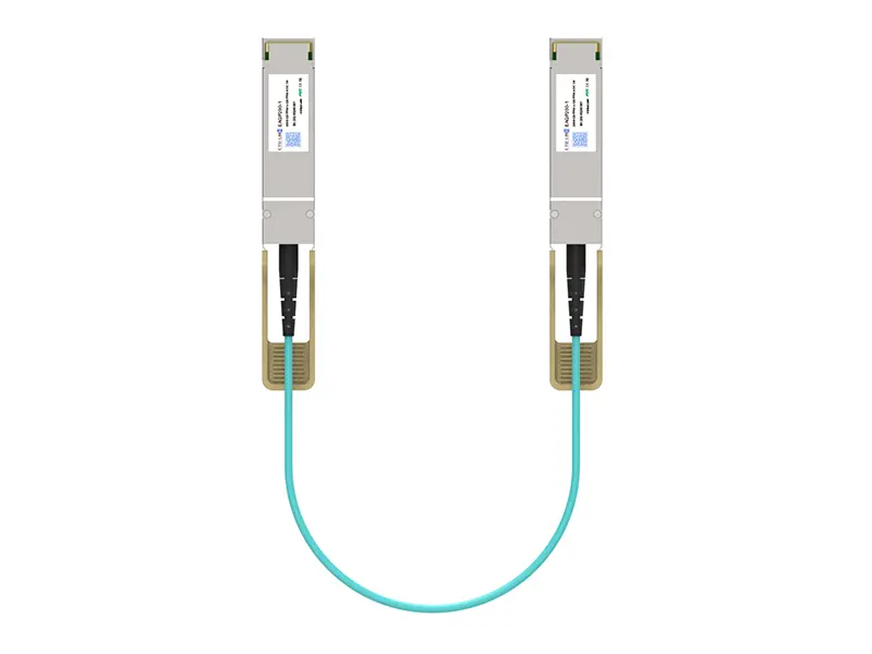 200G QSFP56 AOC
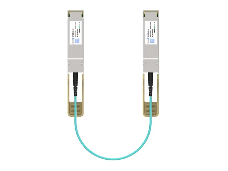 400G QSFP-DD AOC
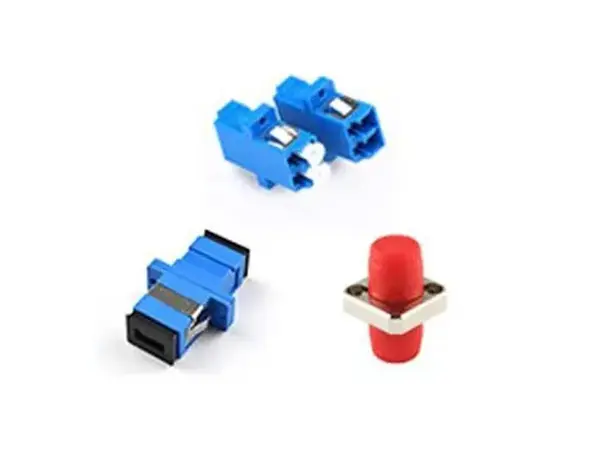 Adapter Details
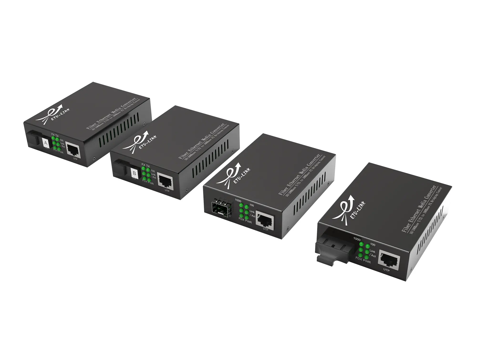 Media Converter
Leave Your Message
Choosing the right 400G OSFP AOC can determine whether a high-speed network remains stable under pressure. Data centers increasingly use 400Gb/s links for spine-leaf switches, artificial intelligence clusters, and demanding storage environments. Yet speed alone does not guarantee a successful installation. Cable design, optical performance, power consumption, connector compatibility, and operating distance all require careful evaluation.
A 400G OSFP AOC combines OSFP transceivers with a factory-terminated active optical cable. This design can simplify deployment and reduce connection errors. It may also provide lower latency and cleaner airflow than several parallel connections. However, not every cable suits every switch. Engineers should verify the switch’s port specification, firmware support, forward error correction requirements, and preferred cable length. A two-meter link may work perfectly inside one rack, while a fifteen-meter route could demand different thermal and routing considerations.
Small details matter.
Reliable selection should come from measured specifications, not attractive product labels. Review insertion loss, bit error rate, temperature range, bend tolerance, and compliance information. Ask whether the supplier performs production testing and provides traceable quality documentation. Field experience also deserves attention. A cable that performs well in a laboratory may behave differently in a crowded rack with limited ventilation.
There is no universal “best” 400G OSFP AOC. The right choice depends on distance, equipment, workload, and future expansion plans. It is easy to overestimate bandwidth and underestimate maintenance. A careful comparison can prevent expensive replacements, although even a well-planned design may need revision after real deployment. This guide examines the practical questions that help network teams choose with greater confidence.
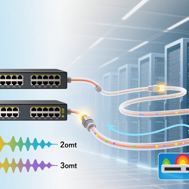
How to Choose the Right 400G OSFP AOC?
A 400G OSFP AOC should match the host’s electrical interface, not only its connector shape. The key reference is 400GAUI-8, which uses eight electrical lanes at approximately 50G each. Each lane carries PAM4 signaling, allowing the assembly to reach 400G aggregate bandwidth. Check whether the switch or network card supports 400GAUI-8 before ordering. A physically compatible module may still fail during link training.
Look closely at the lane structure. An 8×50G PAM4 design keeps eight 50G lanes from the host through the cable assembly. This layout is useful when the equipment exposes eight-lane 400G ports or supports breakout into eight 50G connections. A 4×100G PAM4 design groups capacity into four 100G lanes. It may suit equipment built around four 100G channels, but the host’s gearbox and firmware must support that mapping. The labels can be confusing.
In field checks, I verify port coding, lane mapping, FEC requirements, and cable length together. PAM4 signals have less noise margin than older NRZ links, so connector cleanliness and bend control matter. Ask for the operating temperature range and measured power consumption. Also confirm whether the AOC supports forward error correction on both ends. One overlooked detail can create intermittent errors. I have seen link tests pass briefly, then fail under sustained traffic. That result deserves investigation, not a quick replacement.
| Comparison Dimension | 400GAUI-8 | 8×50G PAM4 | 4×100G PAM4 |
|---|---|---|---|
| Definition | An eight-lane electrical host interface used to transport a nominal 400Gb/s Ethernet signal. | An eight-lane optical architecture in which each lane carries approximately 50Gb/s using PAM4 signaling. | A four-lane optical architecture in which each lane carries approximately 100Gb/s using PAM4 signaling. |
| Primary domain | Electrical interface between the Ethernet host ASIC, switch, or network adapter and the pluggable module. | Optical interface and fiber mapping inside or at the ends of an AOC. | Optical interface and fiber mapping inside or at the ends of an AOC. |
| Number of lanes | 8 electrical lanes | 8 optical lanes | 4 optical lanes or four optical wavelengths, depending on the optical implementation |
| Modulation | PAM4 electrical signaling | PAM4 optical signaling | PAM4 optical signaling |
| Typical baud rate per lane | Approximately 26.5625 GBd per lane | Approximately 26.5625 GBd per lane for a 50Gb/s data lane | Approximately 53.125 GBd per lane for a 100Gb/s data lane |
| Nominal aggregate data rate | 400Gb/s Ethernet payload class | 8 × 50Gb/s = approximately 400Gb/s | 4 × 100Gb/s = approximately 400Gb/s |
| Common Ethernet relationship | Associated with 400G host electrical connectivity and eight-lane module interfaces. | Commonly associated with eight-fiber parallel optics, such as 400GBASE-SR8-style lane mapping. | Commonly associated with four-lane parallel or four-wavelength designs, such as 400GBASE-DR4- and 400GBASE-FR4-style architectures. |
| Fiber count for a duplex AOC | Not applicable; this is an electrical interface definition. | Typically 8 fibers for transmit and 8 fibers for receive, or 16 total fibers in a bidirectional parallel-fiber assembly. | Typically 4 fibers for transmit and 4 fibers for receive in a parallel-fiber design; wavelength-multiplexed designs can use fewer physical fibers. |
| Optical component complexity | Defines the electrical lane interface but does not by itself define the optical engine. | Generally simpler optical lane mapping because each lane uses a dedicated fiber path. | Higher per-lane speed; wavelength multiplexing may reduce fiber count but can increase optical design complexity. |
| Typical AOC advantage | Provides a clear eight-lane electrical compatibility target for a 400G OSFP host port. | Offers straightforward parallel-optics implementation and is suitable for short-reach data-center links. | Uses fewer optical lanes than an eight-lane design and can support more compact fiber interfaces. |
| Main selection concern | Confirm that the switch or adapter port supports 400GAUI-8, including lane rate, electrical compliance, and management requirements. | Confirm the required fiber count, connector type, polarity, reach, and compatibility with the receiving eight-lane optical interface. | Confirm four-lane or wavelength-multiplexed compatibility, optical budget, FEC behavior, and receiver support for 100G PAM4 lanes. |
| OSFP AOC considerations | The OSFP form factor must provide the correct electrical lane mapping and support the host platform's operating and management specifications. | The cable assembly should maintain lane polarity, insertion-loss, return-loss, and bit-error-rate performance across the specified reach. | The cable assembly should meet the higher per-lane signal-integrity requirements and maintain correct lane or wavelength mapping. |
| Best-fit deployment | 400G switch-to-module or adapter-to-module connections where the host port is designed for eight electrical lanes. | Short intra-rack or inter-rack links where parallel-fiber infrastructure is acceptable. | Higher-density links where reducing the number of optical lanes is more important than minimizing optical-engine complexity. |
Note: 400GAUI-8 describes the host-side electrical interface, while 8×50G PAM4 and 4×100G PAM4 describe optical lane architectures. They should not be treated as interchangeable specifications. Actual reach, FEC, connector, power, and management behavior must be verified against the applicable Ethernet standard and the equipment manufacturer's interoperability requirements.