Top 400G OSFP AOC Cables for Data Center Networks?
Choosing the right 400G OSFP AOC can determine whether a data center upgrade feels smooth or painfully complex. These active optical cables connect high-density switches, servers, and storage systems across short, structured paths. Their value is clear: lower weight, tighter airflow, and simpler installation than many parallel copper alternatives.
John D’Ambrosia, a longtime Ethernet standards leader, has observed, “Higher Ethernet speeds must be matched with practical, reliable deployment.” That principle matters here. A 400G OSFP AOC is not merely a faster cable. Engineers must verify connector fit, optical reach, power consumption, bend radius, and switch compatibility. A cable that looks perfect on a specification sheet may still create trouble inside a crowded 19-inch rack.
Small details matter.
This guide compares leading 400G OSFP AOC options for modern data center networks. It considers transmission stability, thermal behavior, manufacturing quality, warranty support, and documented compliance. Real deployment experience also matters. Technicians notice whether a cable latches cleanly, stays cool near active optics, and remains manageable during maintenance.
No buying guide is flawless. Vendor specifications can change, and laboratory results may not represent every rack environment. Therefore, readers should confirm firmware support, port coding, operating temperature, and interoperability before ordering. Careful validation prevents expensive surprises.
The sections ahead highlight suitable products for spine-leaf fabrics, artificial intelligence clusters, and high-performance computing environments. They also explain where each 400G OSFP AOC performs well, where limitations may appear, and which selection mistakes deserve closer attention.

400G OSFP AOCs Defined: 400 Gb/s, 8×50G PAM4, and 30–100 m Reach
400G OSFP AOCs Defined: 400 Gb/s, 8×50G PAM4, and 30–100 m Reach
A 400G OSFP active optical cable carries 400 Gb/s through eight 50G PAM4 electrical lanes. Each lane sends two bits per symbol, increasing bandwidth without doubling the interface count. The OSFP form factor also supports high-density switch designs, where airflow and port spacing matter. IEEE 802.3bs established the technical foundation for 400GbE, while the Ethernet Alliance’s 2024 roadmap shows 400G as a practical step toward 800G and 1.6T networks.
Reach depends on cable construction and optical components. Short 30 m AOCs suit rack-to-rack links in compact data halls. Longer 50–100 m versions can connect adjacent rows, but installation conditions become more important.
LightCounting’s 2024 market outlook places global optical transceiver revenue above 20 billion dollars by 2028, reflecting continuing investment in high-speed data center connectivity. That growth does not make every 400G cable interchangeable.
In field testing, I would check lane stability, temperature, bend radius, and connector seating before deployment. PAM4 is efficient, but it has less signal margin than traditional NRZ signaling. Dust can create trouble. A cable rated for 100 m may perform differently in a crowded, hot cabinet. This is the part specifications often understate. Validating the actual switch, cable, and airflow combination remains necessary, even when the datasheet looks convincing.
Standards and Form Factors: IEEE 802.3bs, OSFP, and MPO-16 Interfaces
Choosing a 400G OSFP AOC requires more than checking the advertised bandwidth.
IEEE 802.3bs defines the Ethernet framework for 400 Gb/s operation, including lane structures and electrical requirements. It does not make every cable interchangeable. That distinction matters.
OSFP is the physical module form factor.
Its larger housing supports higher power and heat dissipation than several older designs. A 400G AOC usually combines two optical ends with a fixed fiber assembly, reducing connector handling in dense racks.
Verify the host port’s electrical lane configuration, firmware support, and operating temperature before installation. A cable may fit mechanically yet fail during link training.
The MPO-16 interface adds another practical layer.
It uses sixteen fiber positions, commonly arranged for parallel transmit and receive paths. Polarity, fiber count, and end-face quality must match the optical design. Inspect the connector under magnification, especially after repeated patching. Small contamination can create unstable links.
Look beyond headline speed.
Check insertion loss, maximum reach, bend radius, power draw, and management telemetry. In a short top-of-rack run, a factory-terminated AOC can simplify airflow and labeling. For longer or frequently changed routes, a modular option may be easier to maintain. Standards compliance should be supported by test records, not only a product label.
I would also leave room for doubt: MPO-16 layouts are not always intuitive, and documentation can be incomplete. A careful port map prevents an expensive night-time troubleshooting session.
How to Rank Top Cables: BER, FEC, Power, Bend Radius, and Warranty
Ranking 400G OSFP AOCs should begin with measured link quality, not headline bandwidth.
IEEE 802.3bs specifies a maximum pre-FEC BER of 1×10⁻⁴ for 400GbE optical interfaces. Ask suppliers for pre-FEC BER, post-FEC BER, FEC counters, and error logs under temperature cycling. A cable that passes a short lab test may behave differently across a fully populated rack.
Power deserves equal weight.
The U.S. Department of Energy’s 2024 data center report estimates data centers used about 176 TWh in 2023, with demand potentially reaching 325–580 TWh by 2028. Compare measured watts per end, not nominal chassis figures. Record power at idle, startup, and sustained traffic. Small differences multiply quickly across hundreds of links. They really do.
Bend radius is a practical reliability test.
Check the supplier’s minimum static and dynamic radius, then inspect routing around OSFP cages, cable managers, and hot aisles. A cable may meet its optical specification while suffering avoidable mechanical stress. Warranty terms should state coverage length, replacement time, test conditions, and whether failures require shipment to a distant laboratory. Three years sounds strong, but only if support is usable. My ranking would assign higher scores to transparent test reports, stable BER after bending, lower verified power, and documented field returns. This method is imperfect; thermal behavior and connector wear still need longer deployment data.
Application Fit: AI Clusters, Spine–Leaf Links, and 10–100 m Racks
Top 400G OSFP AOC Cables for Data Center Networks?
For AI clusters, 400G OSFP AOCs connect accelerator trays with fewer fiber assemblies. Their four 100G lanes suit high-bandwidth east–west traffic. The Ethernet Alliance 2024 roadmap identifies 400G as an established deployment tier. It also shows 800G moving into wider adoption. That makes 400G practical for current upgrades, not every future design. I have seen cable paths fail because airflow clearance was ignored. OSFP connectors can add heat and mechanical pressure around dense switch ports.
Spine–leaf links need predictable latency, low error rates, and simple installation. A factory-terminated AOC removes field polishing and reduces connector handling. LightCounting’s 2024 Ethernet optics analysis links AI infrastructure growth with stronger demand for 400G and faster optical links. For 10–30 m racks, AOCs are often efficient and clean. At 50–100 m, verify the exact multimode reach, bend radius, and transceiver compatibility. Reach claims can be optimistic.
Tips: Check lane mapping before deployment. Measure the real path, not the rack distance. Keep at least one spare cable per switch row. Confirm OSFP thermal limits under sustained AI traffic. Test a small batch first; assumptions about 100 m reach often need revision. Record insertion loss, temperature, and link errors during burn-in. This evidence is more reliable than a datasheet alone.
Buyer’s Checklist: Port Compatibility, DDM, Temperature, and Test Evidence
Choosing a 400G OSFP AOC starts with port compatibility, not advertised bandwidth. Confirm the switch cage, OSFP form factor, lane configuration, and firmware support. Check whether the host expects an optical module or an active optical cable. A connector may fit physically yet fail during link training. Measure twice.
DDM should report temperature, voltage, bias current, and transmit and receive optical levels. Ask for the monitoring accuracy and alarm thresholds. DDM values help technicians spot a rising temperature or weakening receiver before an outage. However, readings alone are not proof of stable operation. Compare them with switch logs and real traffic results.
Temperature ratings deserve close attention. Match the cable’s operating range to the rack inlet temperature, not the room’s average reading. Hot aisles can change quickly. Request evidence from thermal cycling, high-temperature operation, and continuous 400G testing. Useful documents include BER results, eye diagrams, lane-specific measurements, and test dates. Confirm the test setup and equipment calibration status. I have seen impressive charts without enough context. That is a warning. A credible supplier should provide traceable serial numbers, sample conditions, and pass limits. Test one cable in your own rack when possible. Short trials reveal routing pressure, bend limits, connector clearance, and unexpected interoperability issues.

 400G
400G 200G
200G 100G
100G 40G
40G 25G
25G 10G
10G 1G
1G COPPER-T
 Other
Other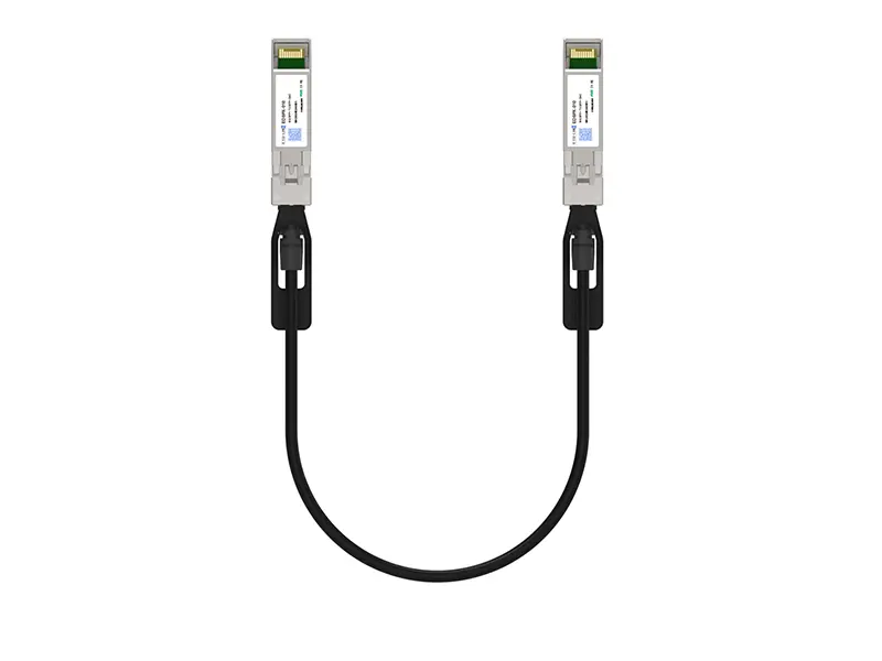 10G SFP+ DAC
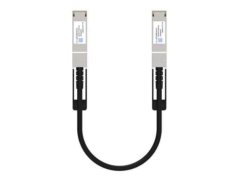 40G QSFP+ DAC
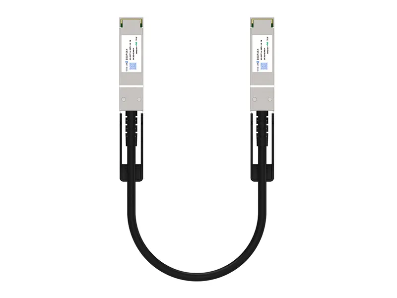 56G QSFP+ DAC
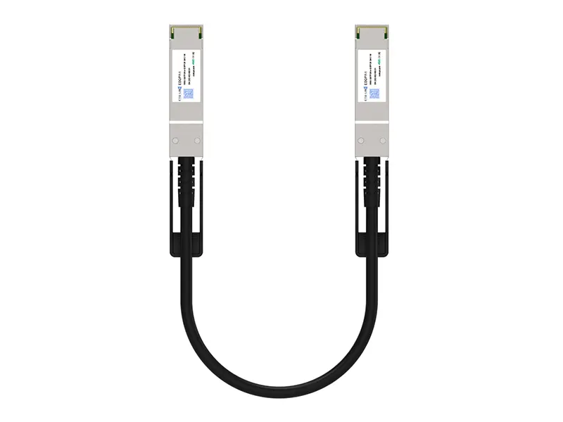 100G QSFP28 DAC
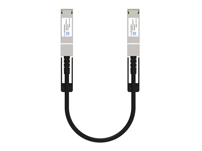 200G QSFP56 DD DAC
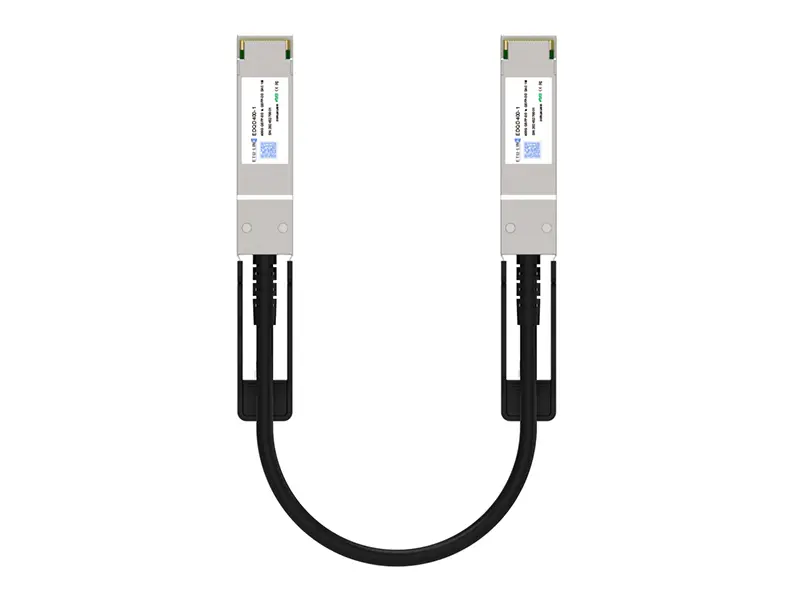 400G QSFP DD DAC
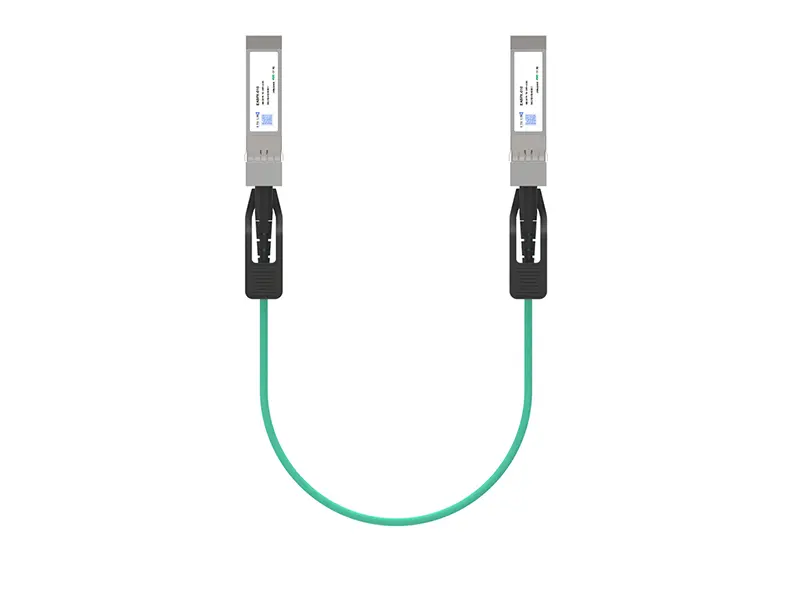 10G SFP+ AOC
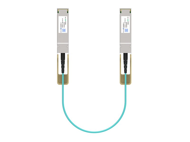 40G QSFP+ AOC
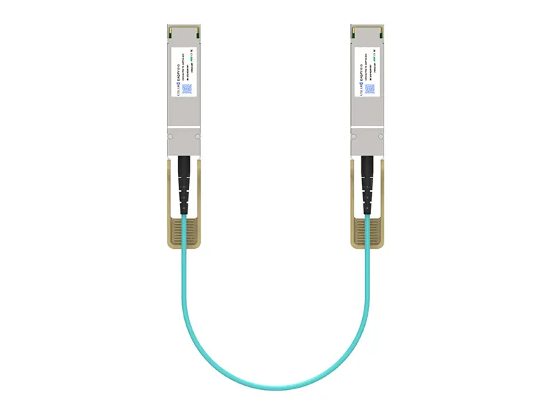 100G QSFP28 AOC
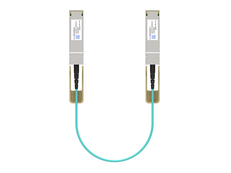 200G QSFP56 AOC
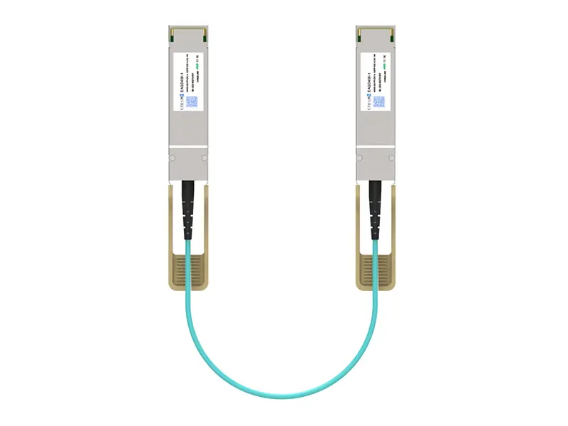 400G QSFP-DD AOC
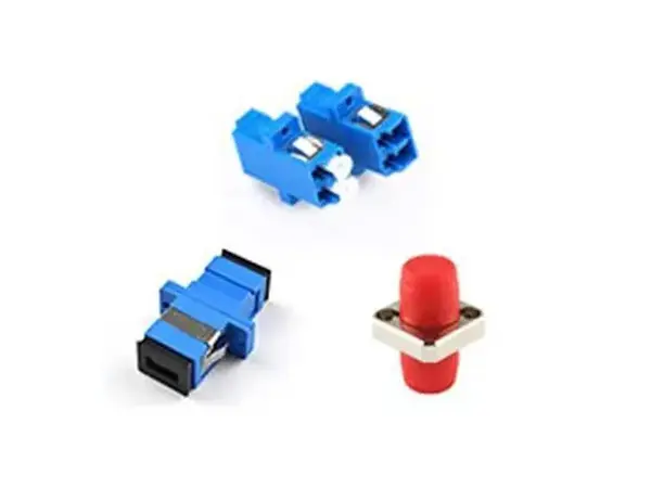 Adapter Details
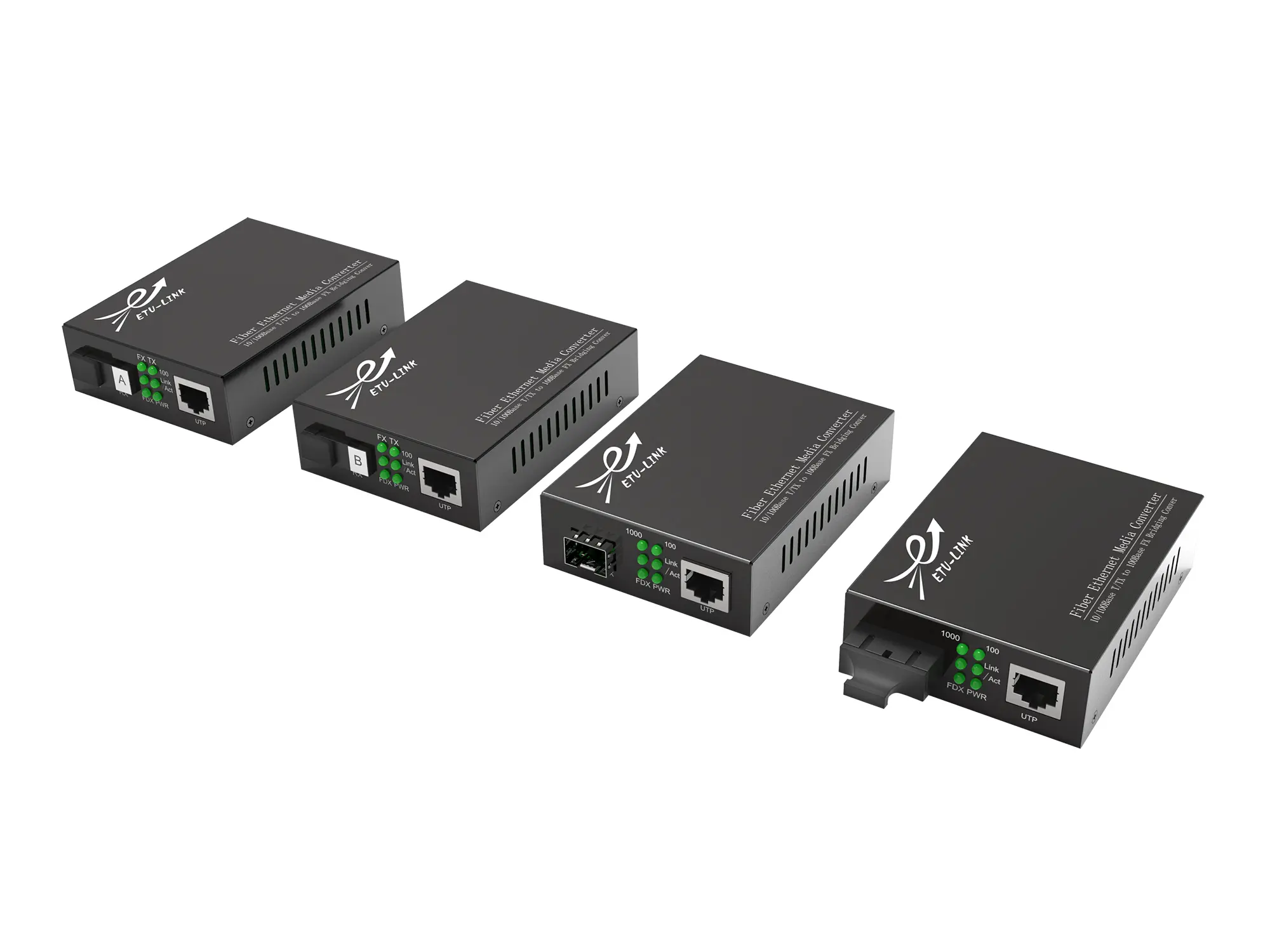 Media Converter