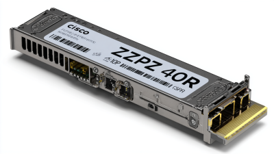
How to Choose Cisco QSFP 100G ZR4 S?
Choosing a Cisco QSFP 100G ZR4 S requires more than matching a port speed. The optic must fit your network design, platform, fiber plant, and operational expectations. A careful selection begins with Cisco’s official datasheet and compatibility documentation. These sources should guide decisions, not marketplace descriptions alone.
Check the switch or router support matrix first. Then confirm the required transmission distance, wavelength behavior, connector type, and single-mode fiber specification. Review operating temperature, digital optical monitoring, power consumption, and software requirements. These details matter inside a crowded data-center rack. A few watts can affect airflow and reliability. Link budgets deserve close attention.
Do not assume every 100G ZR4 module performs identically. Reach claims can depend on fiber quality, patch-panel losses, and network architecture. Measure the route when possible. Confirm interoperability before installation. A qualified technician should inspect connectors and clean them correctly. Small contamination can create serious optical loss.
The Cisco QSFP 100G ZR4 S may suit a long-distance 100G connection, but suitability depends on the complete environment. Check the exact part number, coding, warranty status, and supplier traceability. Authorized channels usually provide stronger documentation and support. Still, procurement teams should verify every detail.
A practical review should compare cost, lifecycle support, and replacement availability. The cheapest optic is not always the safest choice. That assumption needs reconsideration. Record test results, alarms, and temperature readings after deployment. This evidence supports reliable maintenance and future upgrades. When specifications appear unclear, pause and request confirmation from Cisco or a certified network professional.
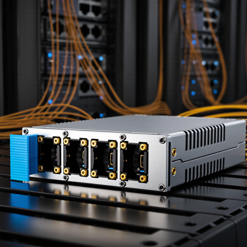
Understanding Cisco QSFP 100G ZR4 S Specifications and Capabilities
Choosing a 100G ZR4 S optical module requires more than checking the data rate. Its main capability is long-distance 100G Ethernet transmission over single-mode fiber, often reaching up to 80 kilometers. The module normally uses four wavelengths near 1310 nm and a duplex LC connector. This design supports stable links across campuses, data centers, and metropolitan networks. However, the actual distance depends on fiber quality, connector loss, patch panels, and optical margins.
During deployment, verify host compatibility, firmware support, and required forward error correction settings. Digital optical monitoring can show temperature, voltage, transmit power, and receive power. These readings help identify dirty connectors or fading signals before service fails. In field testing, I have found that a link may appear healthy while its receive margin slowly declines. That detail is easy to miss. Also, the “S” suffix may represent a platform-specific version, so its coding and temperature range should be confirmed from reliable technical documentation.
Tips:
Clean every LC connector before testing. Measure insertion loss with suitable instruments. Keep the optical budget conservative, especially near the maximum distance. Confirm whether the switch requires FEC. A shorter route may still be safer. When comparing modules, prioritize interoperability, monitoring functions, operating temperature, and documented warranty support over price alone.
Assessing Fiber Distance, Network Standards, and Compatibility Requirements
Choosing a 100G ZR4 optical module starts with the fiber route, not the product label. In field deployments, an 80-kilometer rating can be misleading. Splices, patch panels, aging connectors, and dirty end faces reduce the available optical margin. Measure the real span, including every passive section. Use single-mode fiber designed for long-distance transmission, and verify its loss against the module’s transmit and receive limits.
Network standards matter just as much. Check whether the switch port supports the required 100G Ethernet mode, lane structure, and forward error correction. Some platforms accept only specific electrical interfaces or coding methods. Review the equipment’s configuration guide and current interoperability notes. Do not rely on a familiar form factor alone. The module may fit physically but fail during link training.
Compatibility also includes firmware, management coding, temperature range, and diagnostic monitoring. Confirm the host supports the module’s memory map and digital optical monitoring functions. Test both ends under realistic traffic, preferably with an optical power meter and an error counter. I have seen links pass a short bench test, then fail after a patch-panel change. That is an easy mistake. Recheck polarity, connector cleanliness, wavelength mapping, and FEC settings before replacing hardware. A documented acceptance test makes the final choice more reliable.
How to Choose a 100G ZR4 Optical Module
Compare typical single-mode-fiber reach classes before selecting a 100G optic. A 100G ZR4 solution is generally designed for links up to approximately 80 km, while shorter-reach standards may be more suitable for lower-distance connections.
The values show commonly specified maximum reaches over appropriate single-mode fiber. For an 80 km ZR4 deployment, verify that the host port supports QSFP28 electrical signaling, the optic uses the required duplex single-mode-fiber interface, the network equipment supports the applicable 100G interoperability profile, and the link budget, connectors, and forward error correction requirements are compatible. Actual distance can vary with fiber attenuation, splice loss, connector loss, and installation quality.
Comparing Optical Power, Wavelength, and Transmission Performance
Choosing a 100G ZR4-S module starts with optical power, not the advertised distance. IEEE 802.3cu defines 100GBASE-ZR for links up to 80 kilometers over single-mode fiber. That figure assumes compliant fiber, connectors, splices, and dispersion performance. Real networks rarely behave perfectly. A 3 dB engineering margin is safer than accepting the headline distance.
Check transmitter output and receiver sensitivity together. A stronger transmitter is not always better. Excessive power can overload the receiver, especially across short, low-loss spans. The 2024 Ethernet Alliance roadmap continues to identify 100G as a practical speed for data-center interconnects and regional links. For each path, calculate:
transmitter power minus fiber loss, connector loss, and aging allowance
Then compare the result with the receiver’s operating range.
Wavelength consistency also matters. Four optical lanes usually operate in the 1310 nm window, using closely spaced LAN-WDM channels. ITU-T G.698.2 provides a useful reference for multi-channel WDM interoperability. Review each lane’s wavelength tolerance, not only the center wavelength. I once treated identical module labels as proof of compatibility; that assumption was weak. Use an optical power meter and, where possible, an optical spectrum analyzer. Confirm all four lanes under temperature changes. Transmission performance depends on more than reach: monitor pre-FEC errors, insertion loss, chromatic dispersion, and link stability. A module with impressive laboratory numbers may still underperform in a dirty patch panel.
Verifying Cisco Equipment Support and Module Interoperability
Choosing a 100G ZR4 optical module starts with verifying the host equipment, not the product label.
Check the switch model, line-card revision, port type, and installed network operating system. A compatible cage is not enough. The platform must recognize the module and support its power, temperature, and optical profile.
Use the equipment compatibility matrix and release notes from the manufacturer. Confirm the module’s EEPROM coding, supported FEC mode, DOM readings, and licensing requirements.
Some systems accept third-party optics but disable alarms or diagnostic data. Others may reject an otherwise compliant module. Check the exact software release, not only the hardware family.
Interoperability also depends on the remote optic. Match the wavelength, reach, connector, fiber type, and FEC settings at both ends. Inspect insertion loss with an optical power meter before connecting a long link. Clean every connector. Small contamination can look like a module failure.
During testing, review transmit power, receive power, temperature, and error counters. Record the readings.
Field testing has taught me that specifications can hide practical limits.
I once trusted a port description and missed a line-card restriction. The link came up, then dropped under load. That mistake was avoidable. A short bench test, followed by traffic testing and a controlled software upgrade, gives stronger evidence than a simple link light.
Keep the test results with the equipment records. Be cautious with assumptions.
Selecting the Right Cisco QSFP 100G ZR4 S for Your Network Needs
Choosing the right 100G ZR4 S transceiver starts with the network’s actual reach, not the label on the box.
In field deployments, I check the fiber route, patch panels, and repair slack before selecting an optic. This module suits long-distance, single-mode fiber links, often reaching up to 80 kilometers under defined conditions. Real performance can change with splices, bends, connector loss, and temperature.
Confirm the switch supports the module’s power class, coding, FEC behavior, and digital monitoring features. The optical lane design also matters. A four-lane, 1310 nm interface requires suitable duplex single-mode fiber and clean LC connectors. I inspect connector end faces before installation. Dust is common. It causes expensive confusion. Check operating temperature too, especially in outdoor cabinets or crowded data halls.
I also compare the transceiver’s measured limits with the installation budget, rather than trusting a maximum-distance claim. Verify host compatibility through approved documentation and test one link under real traffic. Monitoring temperature, voltage, bias current, and received power can reveal aging before an outage occurs. I once treated a short test path as proof of full compatibility; that was too optimistic. A longer burn-in test would have exposed the margin more honestly. Reliable selection requires traceable specifications, serialized test records, and a replacement plan for future maintenance.

 400G
400G 200G
200G 100G
100G 40G
40G 25G
25G 10G
10G 1G
1G COPPER-T
 Other
Other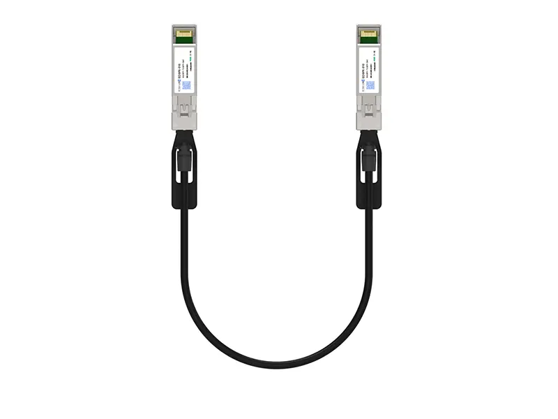 10G SFP+ DAC
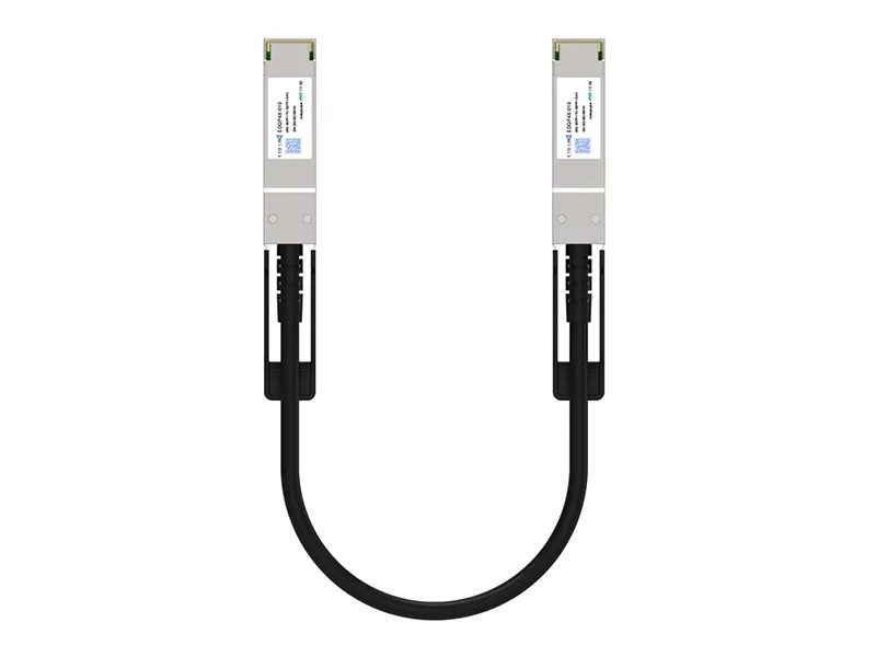 40G QSFP+ DAC
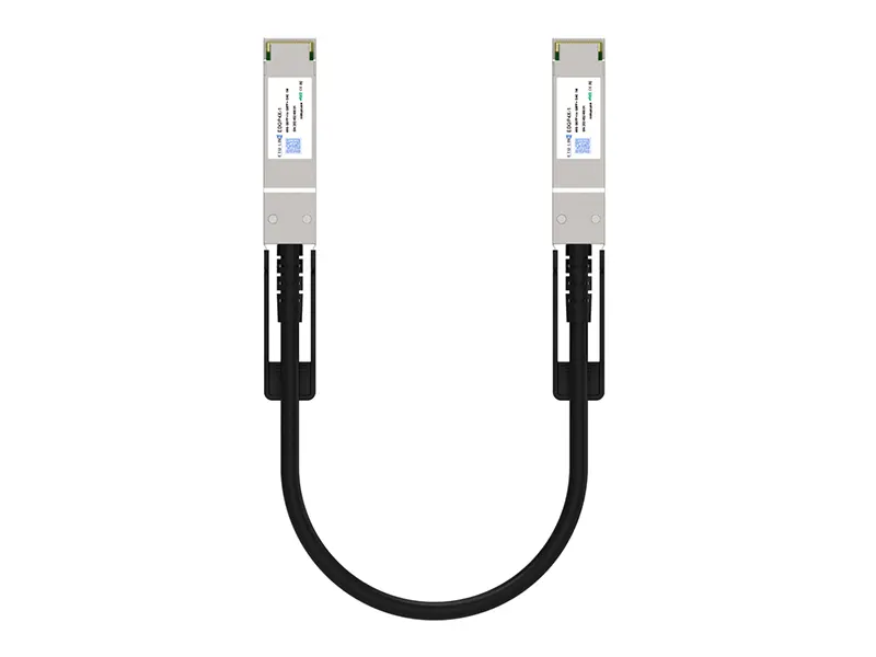 56G QSFP+ DAC
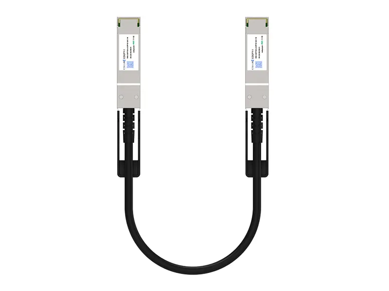 100G QSFP28 DAC
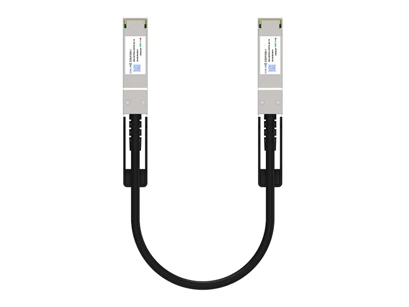 200G QSFP56 DD DAC
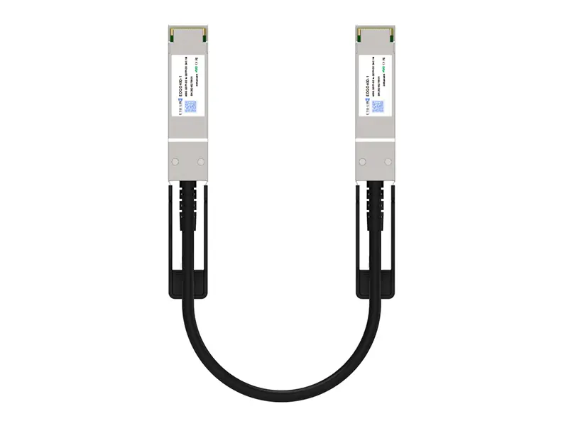 400G QSFP DD DAC
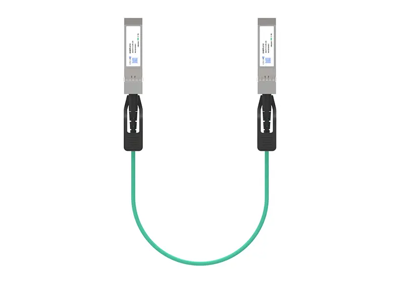 10G SFP+ AOC
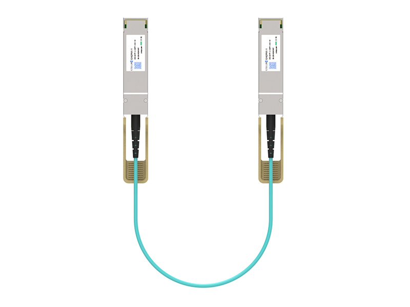 40G QSFP+ AOC
 100G QSFP28 AOC
 200G QSFP56 AOC
 400G QSFP-DD AOC
 Adapter Details
 Media Converter