What Is a 10GbE SFP+ Transceiver?
A 10GbE SFP+ Transceiver is a compact, hot-swappable module that connects network equipment at 10 gigabits per second. It fits into SFP+ ports on switches, routers, servers, and network interface cards. Unlike a complete network cable, the transceiver converts electrical signals into optical or copper signals. This small distinction matters during network planning.
In practical deployments, engineers select modules according to cable type, distance, wavelength, and port compatibility. SR models commonly use multimode fiber for shorter links inside data centers. LR models typically use single-mode fiber for longer connections between buildings or equipment rooms. Direct-attach copper cables can provide a lower-cost option for short rack connections. The correct choice prevents wasted ports, unstable links, and unnecessary replacement work.
Reliable installation requires more than matching the speed rating. Check connector types, fiber polarity, switch compatibility, operating temperature, and digital optical monitoring support. Vendor coding can also affect whether a module is accepted by specific equipment. Testing matters. A link may show 10Gbps while still suffering from poor fiber cleaning or excessive optical loss. That is easy to overlook.
This guide explains how a 10GbE SFP+ Transceiver works, where each type fits, and which specifications deserve attention. It also considers practical limits, including power consumption, heat, and interoperability. Some recommendations depend on the environment. There is no universal module. Real networks are less tidy than product tables suggest.
Definition and Purpose of a 10GbE SFP+ Transceiver
A 10GbE SFP+ transceiver is a compact, hot-swappable module that connects network equipment to a 10 Gigabit Ethernet link. “SFP+” describes the form factor, while “10GbE” describes the transmission speed. Under IEEE 802.3ae, the link rate is 10 Gb/s, although usable throughput is slightly lower after protocol overhead. The module converts electrical signals from a switch or server into optical or copper signals for a network cable.
Its purpose is practical: extend connections, reduce cabling limits, and support fast traffic between servers, storage systems, and switches. Fiber versions commonly support distances from several hundred meters to multiple kilometers, depending on the optical design. Direct-attach copper cables usually serve shorter connections. SFF-8431 and SFF-8472 provide important mechanical, electrical, and diagnostic guidance for compatible modules.
Industry data supports the continued relevance of this interface. The Ethernet Alliance’s 2024 Ethernet Roadmap identifies 10GbE as an established deployment speed, while higher rates continue expanding in data centers. IDC’s Worldwide Ethernet Switch Tracker also shows sustained growth in Ethernet switching demand, driven by cloud services and distributed workloads. That does not make every 10GbE module suitable. Cable length, fiber type, temperature, power draw, and device coding still require careful checking.
A label can mislead.
Field testing may reveal unexpected issues, especially with mixed equipment. Digital diagnostics help, but they are not a substitute for compatibility testing.
Key Components and How the Transceiver Works
A 10GbE SFP+ transceiver is a compact module that connects network equipment to a high-speed fiber link. It fits inside an SFP+ cage on a switch, server adapter, or storage device. Its main components include a transmitter, receiver, driver circuit, monitoring chip, and electrical connector. Optical versions also contain a laser or VCSEL and a photodiode. Copper variants use electrical signaling instead.
The host equipment sends differential electrical data into the module. The driver converts this signal into controlled light pulses. These pulses travel through the fiber at 10 gigabits per second. At the receiving end, a photodiode changes light into electrical current. A transimpedance amplifier strengthens the weak signal, while a limiting amplifier reshapes it for the host device. The management interface reports temperature, voltage, and optical power. These readings help technicians locate unstable links.
Small details matter. Clean fiber ends before connection. Respect the cable’s bend radius. Match the fiber type, wavelength, and transmission distance. A single mismatch can cause packet loss or prevent the link from rising. In practical testing, checking diagnostic readings is often faster than replacing every component. Still, monitoring data is not perfect. A normal optical value cannot always reveal contamination or intermittent damage. Inspect connectors and test with a known-good cable when results seem unclear. A tidy installation can still fail.
Supported Fiber, Copper, and Transmission Distance Options
What Is a 10GbE SFP+ Transceiver?
Supported Fiber, Copper, and Transmission Distance Options
A 10GbE SFP+ transceiver converts electrical network signals into optical or copper signals. Its practical reach depends on the selected media. IEEE 802.3-2022 specifies 10GBASE-SR for multimode fiber, typically reaching 300 meters over OM3 and 400 meters over OM4. These links suit server rooms and short data-center rows. They usually use duplex LC connectors and two fiber strands.
For longer connections, 10GBASE-LR uses single-mode fiber and supports distances up to 10 kilometers. Installation quality still matters. Dirty connectors, tight bends, and poor splicing can reduce the real operating margin. The Telecommunications Industry Association recommends structured cabling practices in TIA-568.3-D, including polarity and testing requirements. The number sounds simple. Field results are not always simple.
Copper options include passive direct-attach cables and 10GBASE-T SFP+ modules. Passive cables commonly support short links, often up to seven meters, while active versions can extend farther. A 10GBASE-T module may support up to 100 meters over balanced Category 6A cabling, consistent with TIA-568.2-D channel guidance. However, copper modules often consume more power and may add latency. Measure the complete channel, not only the transceiver label. Fiber offers cleaner long-distance transmission, while copper can reduce cost for nearby equipment. According to the IEEE standard, interoperability also depends on matching wavelength, encoding, connector type, and reach class.
Compatibility, Data Standards, and Network Requirements
What Is a 10GbE SFP+ Transceiver?
A 10GbE SFP+ transceiver converts electrical Ethernet signals into optical or copper signals. It supports 10 Gigabit Ethernet through a compact, hot-swappable port. Compatibility depends on more than the connector. Check the switch port, module coding, wavelength, fiber type, and supported distance. The IEEE 802.3 standard defines common modes, including 10GBASE-SR for multimode fiber and 10GBASE-LR for single-mode fiber. SR commonly reaches 300 meters on OM3 fiber and 400 meters on OM4 fiber. LR can reach about 10 kilometers over suitable single-mode fiber. These figures assume clean links and correct installation.
Network requirements are easy to underestimate. The host device needs a 10GbE-capable port, stable cooling, and enough switching capacity. A copper DAC may suit a short rack connection, while optical modules fit longer links or separate rooms. The ITU Facts and Figures 2023 report estimated 5.4 billion people were online, increasing pressure on data centers and access networks. Yet more bandwidth does not repair poor cabling. I have seen link failures caused by mismatched fiber polarity, not defective modules. That small detail deserves attention.
Tips: Confirm both ends use the same standard and wavelength. Keep a short compatibility record. Test insertion loss before deployment. Vendor coding can still create surprises, so verify approved module support before buying in volume. A 10GbE upgrade may look simple, but the physical layer often needs the most careful review.
10GbE SFP+ Transceiver Compatibility, Standards, and Reach
This chart compares common 10GbE physical-layer options used with SFP+ ports. Passive DAC cables are suited to short data-center links, multimode-fiber SR commonly reaches up to 300–400 meters depending on the fiber grade, while single-mode-fiber LR and ER support approximately 10 km and 40 km respectively. Network devices, optical fiber type, connector configuration, and wavelength must be compatible with the selected standard.

 400G
400G 200G
200G 100G
100G 40G
40G 25G
25G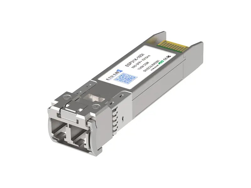 10G
10G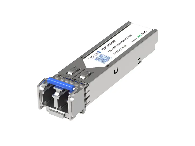 1G
1G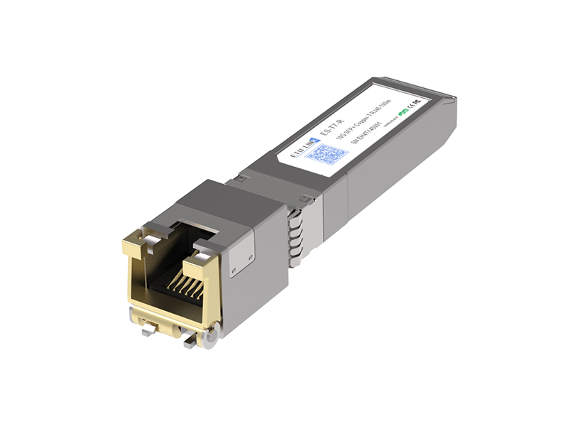 COPPER-T
 Other
Other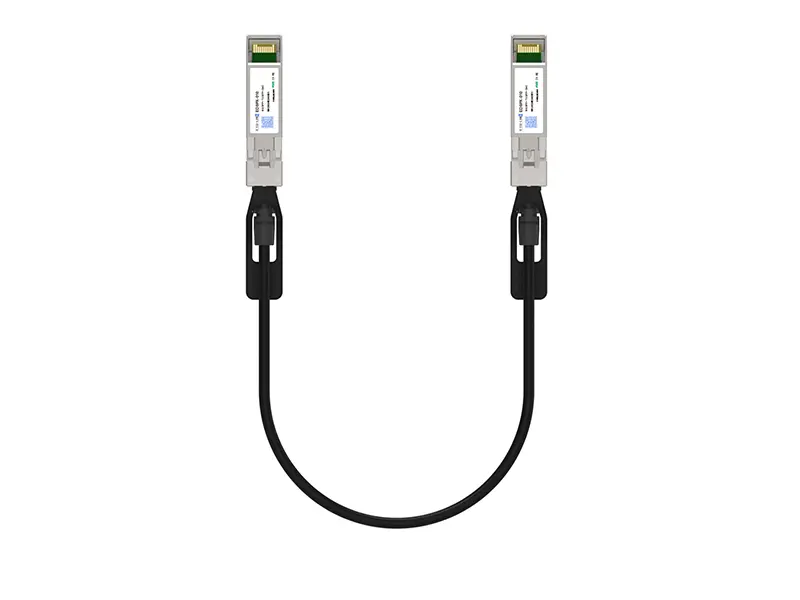 10G SFP+ DAC
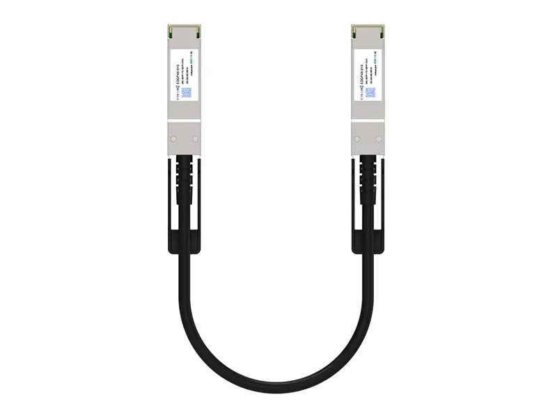 40G QSFP+ DAC
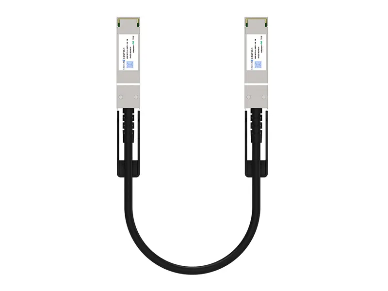 56G QSFP+ DAC
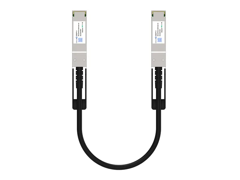 100G QSFP28 DAC
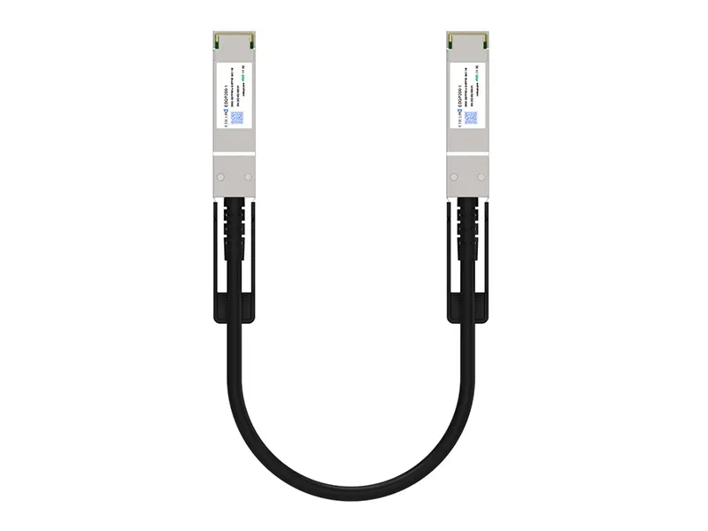 200G QSFP56 DD DAC
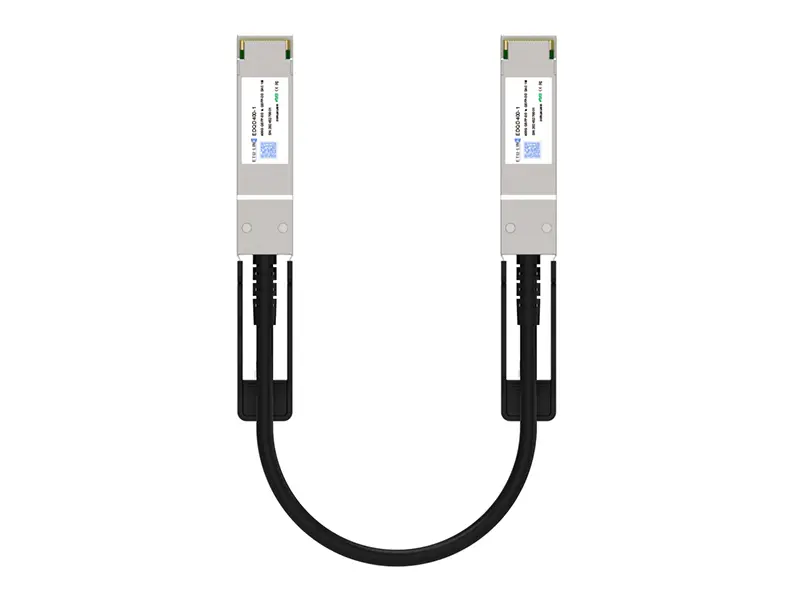 400G QSFP DD DAC
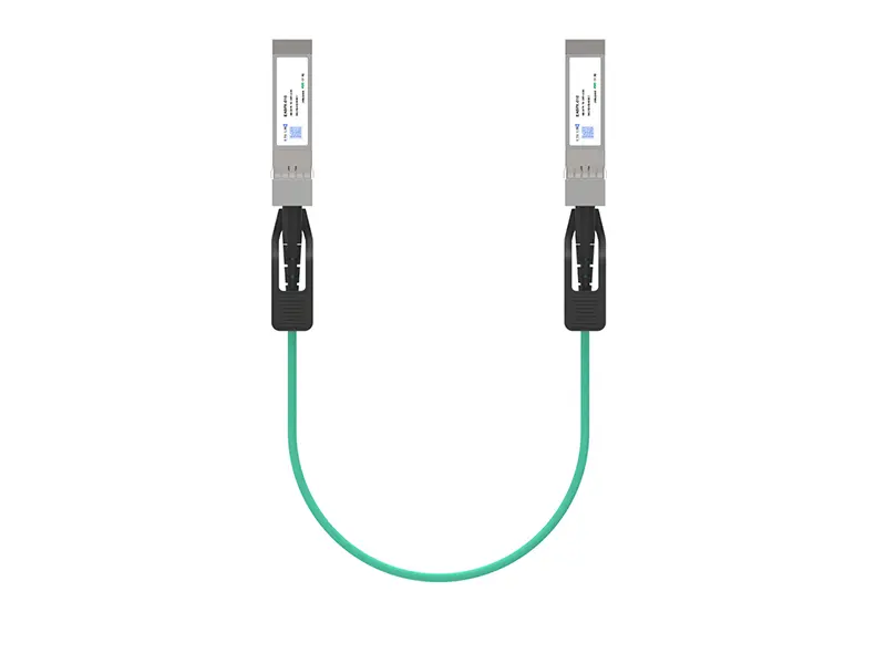 10G SFP+ AOC
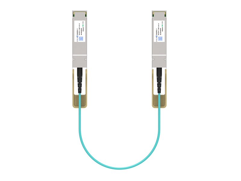 40G QSFP+ AOC
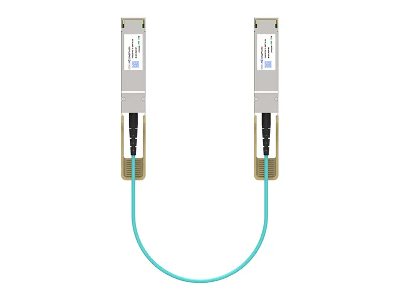 100G QSFP28 AOC
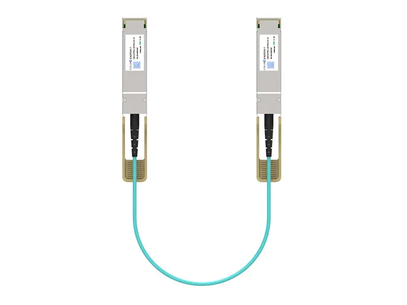 200G QSFP56 AOC
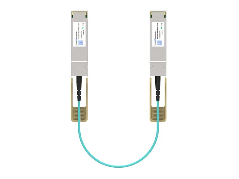 400G QSFP-DD AOC
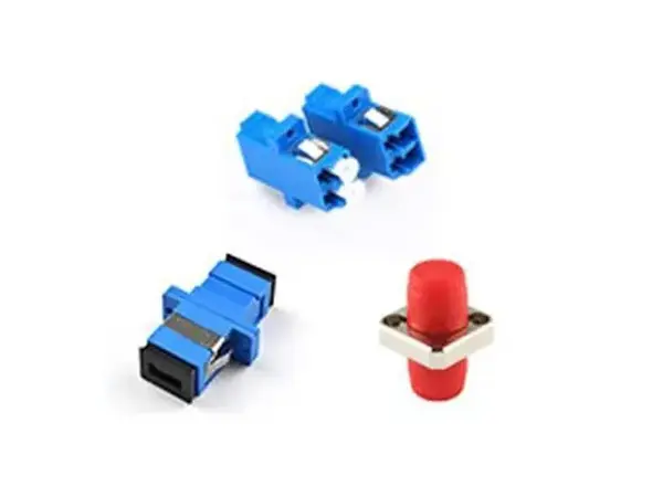 Adapter Details
 Media Converter